- Title
-
Spatiotemporal Coordination of FGF and Shh Signaling Underlies the Specification of Myoblasts in the Zebrafish Embryo
- Authors
- Yin, J., Lee, R., Ono, Y., Ingham, P.W., Saunders, T.E.
- Source
- Full text @ Dev. Cell
|
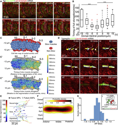
Morphogenesis of Adaxial Cells and the Determination of MPs from DV Midline (A)Time-lapse of the muscle morphogenesis of adaxial cells from segmentation (i) to 140 min after segmentation (viii). Anterior to the left and dorsal to the top in all parasagittal views unless otherwise stated. Timing refers to the relative time after the formation of corresponding somite in all figures unless otherwise stated. White brackets label fully elongated adaxial cells. White dash lines denote somite boundaries unless otherwise stated. Images are taken at somite 18–20. (B) The timing of elongation of each individual adaxial cell at different positions relative to DV midline (nCells = 135, from total of 8 somites taken from 8 embryos, ∗∗∗p < 0.001, Student’s t test). (C–Cʹʹ) Mapping of all slow muscles from four contiguous somites back to the PSM with colors denoting distinct cell fates (C), timing of elongation relative to the segmentation of somite S0 (Cʹ) or relative to the segmentation of each somite (Cʹʹ). Black dash lines label the position of notochord. White asterisks in (C) label the adaxial cells lying on the dorsal or ventral margin of the notochord. (D) Time-lapse of MP differentiation with the live MP cell fate marker eng2a:GFP from PSM (i) to 290 min later (ix). Images are taken at somite 19–20. (E) 2D representation of the adaxial cell rearrangement during slow muscle myogenesis. The varying colors in each track denote the corresponding time relative to the somite segmentation. Black circles and squares denote to the initial positions of future SSFs and MPs, respectively. (F) Probability map of MP initial position constructed from adaxial cell positions in S0 (nSomites = 52, nEmbryos = 16). Left, right, top and bottom refer to anterior, posterior, dorsal and ventral side of adaxial cell population, respectivel. (G) Distribution of AP-Bias of the quantified 52 somite. (i) The AP-Bias in each somite is defined by log(∑area(A)/∑area(P)). ∑area(A) and ∑area(P) denote the area taken by the future MPs anteriorly and posteriorly in the somite, respectively. |
|
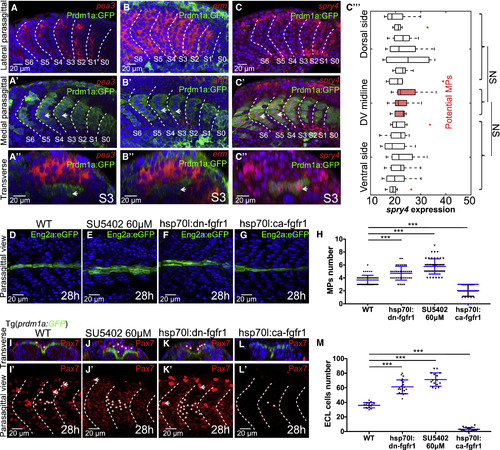
FGF Signaling Participates in the Further Differentiation of Both Slow and Fast Muscle Lineages (A–C) Fluorescent in situ of FGF downstream activators pea3 (A–Aʹʹ) and erm (B–Bʹʹ) and inhibitor spry4 (C–Cʹʹ). Images are taken at the lateral somitic cells (A–C) and the slow muscle fibers (Aʹ–Cʹ) at 18-somite stage. Constructed transverse images are taken at somite S3 and are displayed in (Aʹʹ–Cʹʹ) with lateral to the top and dorsal to the left. Slow muscles are labeled with Prdm1a:GFP and white short arrows. (Cʹʹʹ) Spry4 expression level per cell along the DV axis. The expression of spry4 is measured cell by cell by calculating the average intensity within the nucleus (nCells = 153, from total of 9 somites taken from 5 embryos, NSp > 0.05, Student’s t test). (D–H) Perturbations of FGF signaling change the number of MPs with MPs identified by Eng2a:eGFP expression. Wild-type embryo (D), SU5402 treatment at 60 μM (E), heat shock of hsp70l:dn-fgfr1-eGFP (F), and heat shock of hsp70l:ca-fgfr1 (G) analyzed, all imaged at 28 hpf at muscle segments 16–20, with quantification of MP number shown in (H), where nSegments = 55, 60, 40, and 40 (from 11, 12, 10, and 10 embryos) for conditions (D–G), respectively. (I–L) Perturbations of FGF signaling change the number of ECL cells, with ECL cells identified by Pax7 antibody staining. White asterisks label ECL cells with moderate Pax7 intensity. The much brighter cells labeled with white short arrows are neural crest cells. Wild-type embryo (I and Iʹ), SU5402 treatment at 60 μM (J and Jʹ), heat shock of hsp70l:dn-fgfr1 (K and Kʹ) and heat shock of hsp70l:ca-fgfr1 (L and Lʹ) analyzed at 28 hpf at muscle segments 16–20. Transverse views shown in (I–L) with lateral to the top and dorsal to the left. (M) Quantification of ECL cell number, where nSegments = 16, 21, 15, and 19 (from 6 embryos in each condition) for conditions (I–L), respectively. ∗∗∗p < 0.001, Student’s t test. EXPRESSION / LABELING:
PHENOTYPE:
|
|
The Direct and Indirect Roles of FGF Signaling in the Further Differentiation of Fast and Slow Lineages, Respectively (A–D) Mosaic FGF perturbations in slow muscle cells driven by smyhc1:gal4;UAS:dn-fgfr1-p2a-mCherry (A) or smyhc1:gal4;UAS:ca-fgfr1-p2a-mCherry (Aʹ), respectively. (B and C) Mosaic FGF inhibition (B) or over-activation (C) in the slow muscle fibers is identifiable through mCherry expression. Images are taken at 28 hpf at muscle segments 13–16 and projected along ML axis. (Bʹ–Cʹ) Transverse views of (B and C) made at the sites of dash lines with lateral to the left and dorsal to the top. (D) Fraction of mCherry positive MPs among mCherry positive slow muscles in control group (60/296), FGF inhibited group (52/262), and FGF over-activated group (45/214). (E–G) Mosaic FGF perturbations regardless of cell types with the expression of dn-fgfr1-mCherry (E) or ca-fgfr1-p2a-mCherrry (F) driven by heat shockpromoter hsp70l. The perturbed cells are identifiable through membrane localized dn-fgfr1-mCherry (E) or uniformly distributed mCherry, respectively (F), and labeled with white short arrows. (Eʹ–Fʹ) Transverse views of (E and F) made at the sites of dash lines with lateral to the left and dorsal to the top. (G) Fraction of mCherry positiveECL cells among the total population of mCherry positive cells in fast muscle lineage (both fast muscle fibers and ECL cells) in control group (104/495), FGF inhibited group (373/777), and FGF over-activated group (41/696). Heat shock was performed at 16-somite stage. The quantification of cell fates was performed at muscle segments 16–22 at 30 hpf. |
|
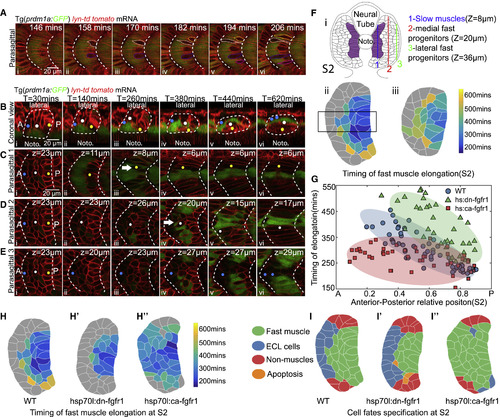
AP Polarity of Fast Muscle Myogenesis and the Roles of FGF Signaling in the AP Patterning (A) Time-lapse of the earliest fast muscle elongation and the displacement of slow muscles. Yellow, white, blue, and magenta labels the contours of elongating fast muscle progenitors. Slow muscles are labeled with Prdm1a:GFP. (B–E) Time-lapse of the cell rearrangement and differentiation of lateral somitic cells throughout the primary myogenesis at coronal view (B) with lateral to the top and anterior to the left and parasagittal optical views (C–E). Yellow, white, and blue circles label cells from posterior (C), central (D) and anterior (E) part of somite S2. In (C)–(E), the z-plane selected corresponds to the position of the center of each cell being tracked; corresponding z-position is clear in (B). White arrows label the elongating fast muscle progenitors. (F) Maps of the timing of fast muscle elongation constructed at somite stage S2 (i) at parasagittal planes 20 μm (ii) or 36 μm (iii) away from the notochord. Cells labeled with gray color did not elongate throughout the primary myogenesis. (G) The timing of elongation of fast muscle progenitors quantified from the rectangle region of (Fii) along the AP axis in wild-type embryo (blue, nCells = 57 from total of 7 somites taken from 6 embryos), embryos under heat shock of hsp70l:dn-fgfr1-eGFP (green, nCells = 35 from total of 6 somites taken from 5 embryos), or heat shock of hsp70l:ca-fgfr1 (red, nCells = 45 from total of 6 somites taken from 5 embryos). The ellipse represents the minimum-volume covering of data points in each group. (H and I) Maps of timing of fast muscle elongation (H–Hʹʹ) and cell fates (I–Iʹʹ) at somite stage S2 in in wild-type embryo (H and I), embryos under heat shock of hsp70l:dn-fgfr1-eGFP (Hʹ and Iʹ), or heat shock of hsp70l:ca-fgfr1 (Hʹʹ and Iʹʹ). Images above are taken at somite 16–18. |
|
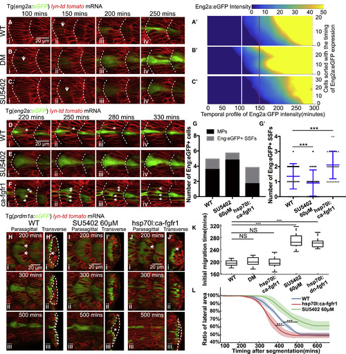
FGF Signaling Determines MP Cell Fate by Regulating Slow Muscle Migration (A–C) Time lapses of Eng2a:eGFP expression during MP differentiation in wild-type embryos (A), embryos under treatment of dorsomorphin (DM) at 50 μM (B), or SU5402 at 60 μM (C). White short arrows denote the onset of Eng2a:eGFP expression that can be identified. (Aʹ–Cʹ) The corresponding temporal expression profile of Eng2a:eGFP for individual MP under same conditions of (A–C). All the MPs in each group are sorted along the y axis according to the timing of initial Eng2a:eGFP expression. The color map represents differential intensity of Eng2a:eGFP for each cell. White and red lines label the start and end of the time window for the onset of Eng2a:eGFP expression. (Aʹ) (nCells = 22 from total of 6 somites taken from 5 embryos); (Bʹ) (nCells = 28 from total of 6 somites taken from 4 embryos); (Cʹ) (nCells = 34 from total of 7 somites taken from 5 embryos). (D–F) Time lapses of Eng2a:eGFP expression in MPs and Eng2a:eGFP+ SSFs in wild-type embryos (D), embryos under treatment of SU5402 at 60 μM (E), and heat shock of hsp70l:ca-fgfr1 (F). White short arrows label Eng2a:eGFP+ SSFs. (G and Gʹ) The number of MPs and Eng2a:eGFP+ SSFs (Gʹ) per muscle segments in conditions of (D)–(F) (nSegments = 31, 22, 28, nEmbryos = 7, 7, 5, ∗∗∗p < 0.001, Student’s t test). (H–J) Time lapses of slow muscle migration in wild-type embryos (H), embryos under treatment of SU5402 at 60 μM (I), or heat shock of hsp70l:ca-fgfr1 (J). Slow muscles are identified by the expression of Prdm1a:GFP. (Hʹ–Jʹ) The reconstructed transverse view of (H)–(J) with medial to the left and dorsal to the top. White arrows denote the breaking of the slow muscle monolayer by fast muscle elongation. Dash lines label the area at the lateral side of slow muscles. White asterisk in (Iʹ iii) denotes the ectopic ECL cells under SU5402 treatment. (K) Timing of the initiation of lateral migration in wild-type embryos (nSomites = 15 from 5 embryos), embryos under dorsomorphin (DM) treatment at 50 μM (nSomites = 12 from 5 embryos), heat shock of hsp70l:ca-fgfr1 (nSomites = 12 from 5 embryos), SU5402 treatment at 60 μM (nSomites = 15 from 5 embryos), and heat shock of hsp70l:dn-fgfr1-eGFP (nSomites = 15 from 5 embryos) (∗∗∗p < 0.001, NSp > 0.05, Student’s t test). (L) The relative size of lateral area (labeled with dash lines in Figures 6H–6J) throughout the lateral migration of SSFs. Blue, green, and red denote the profiles under conditions of (H)–(J) (total of 5 somites from 5 separate embryos in each condition). ∗∗∗p < 0.001, Student’s t test. Images taken at muscle segments 16–18. |
|
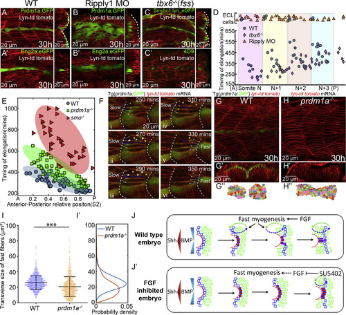
Reciprocal Interactions of Fast and Slow Muscle Fibers Guides Their Differentiation (A–C) The lateral migration of SSFs (A–C) and MPs specification (Aʹ–Cʹ) in wild-type embryos (A), Ripply1 morphants (B), and tbx6−/− mutants (C). Slow muscles are either labeled with Prdm1a:GFP (A and B) or Smyhc1:lyn_eGFP (C). MPs are either labeled with Eng2a:eGFP (Aʹ and Bʹ) or 4D9 antibody (Cʹ). Images are taken at muscle segments 12–16 at 30 hpf. (D) The timing of elongation of individual fast muscle progenitors along the DV midline from a region corresponding to four adjacent somites. Shaded regions represent individual somites in wild-type embryos. Blue, orange, and violet dots denote cells from wild-type embryos (nEmbryos = 5), Ripply1 morphants (nEmbryos = 5), and tbx6−/−mutants (nEmbryos=5), respectively. Cells with ECL cell fate are placed at the top of the panel. (E) AP dependence of the timing of elongation relative to somite segmentation of individual fast muscle progenitors along the DV midline in wild-type embryos (nCells = 57 from total of 7 somites taken from 6 embryos), prdm1a−/− (nCells = 70 from total of 6 somites taken from 6 different embryos), and smo−/− mutants (nCells = 42, from total of 4 somites taken from 4 different embryos). The ellipse represents the minimum-volume covering of data points in each group. (F) Time-lapse of the patterning of fast muscle fibers in wild-type embryos at muscle segments 16–18. The fusing fast muscle progenitors are labeled with blue and yellow asterisks. White short arrows label the dissolving membrane between the fusing cells. The intercalated slow and fast muscles are labeled with long white arrows. (G–H) Parasagittal optical view of wild-type embryos and prdm1a−/− mutant labeled with membrane marker lyn-td tomato at muscle segments 12–15. Transverse views of (G) and (H) are displayed in (Gʹ) and (Hʹ) with dorsal to the left and lateral to the top and manually segmented in (Gʹʹ) and (Hʹʹ). (I) Distribution of the transverse size of fast muscle fibers in wild-type embryo (nCells = 1246 from total of 15 muscle segments taken from 8 embryos) and prdm1a−/− mutant (nCells = 1126 from total of 12 muscle segments taken from 6 embryos) (∗∗∗p < 0.001, Student’s t test). (Iʹ) Probability density of (I). (J) Schematic presentation of how FGF signaling regulates MPs differentiation in wild-type embryos by precisely controlling the timing of SSFs migration and hence their exposure to Shh and BMP signaling. (Jʹ) In the absence of FGF signaling, ectopic MPs are induced not only at the expense of eng+ SSFs but also in an extended time window due to the delay of lateral migration. PHENOTYPE:
|
|
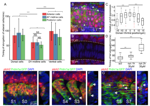
Role of Shh signaling in the waves of adaxial cell elongation along D-V axis, related to Figure 2 (A) The timing of elongation of adaxial cells at different AP and DV positions. Red, blue and green denote adaxial cells from anterior-most part, central part and posterior-most part of adaxial cell population ( nCells=135 from total of 8 somites from 8 different embryos). (B-B’) Fluorescent in situ of ptch2 at PSM on the plane of adaxial cells (B) or the notochord (B’). White short arrow and white asterisks denote the adaxial cells with relative low and high ptch2 expression respectively. Images are taken at 18-somite stage at PSM. (C) Ptch2 expression level per cell along the DV axis. (nCells=101 from total of 5 somites from 5 different embryos). Adaxial cells are labeled with Prdm1a:GFP. (D) Timing of elongation of midline adaxial cells in wild type embryos (nCells=37), embryos under 1 hour (nCells=34) or 2 hours (nCells=47) cyclopamine treatment at 30μM. The cyclopamine treatment was performed at 1 hour or 2 hours before the start of live-imaging. Adaxial cells of somite S0 were then quantified for their timing of elongation. (E-G) Fluorescent in situ of ptch2 within adaxial cells and slow muscle fibers at different stages: (E) PSM and S1; (F) S3 and S4; (G)S7 and S8. (E’-G’) Constructed transverse images of (E-G) with dorsal to the top and medial to the left. White arrows and asterisks denote SSFs that had losing ptch2 expression and MPs that sustained ptch2 expression respectively. Adaxial cells and Slow muscles are labeled with Prdm1a:GFP. ***p < 0.001, NSP >0.05, Student’s t test. |
|
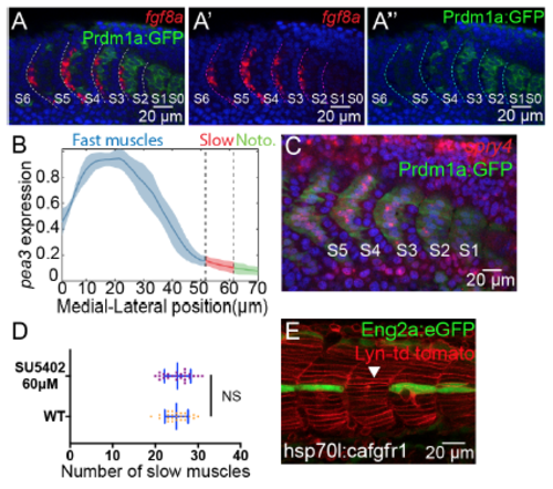
FGF target RNA expression in the myotome and phenotypes of FGF perturbations, related to Figure 3 (A-A’’) Fluorescent in situ of fgf8a from somite S0 to S6 at the parasagittal optical view. Slow muscles are labeled with Prdm1:GFP. Fgf8a and Prdm1:GFP are separately displayed in (A’) and (A’’). Images are taken at somite 15-21 (S6-S0). (B) Quantification of pea3 intensity along the ML axis (nSomites=6 from 6 different embryos). (C) Spry4 expression in somite S1 to S6 by fluorescent in situ of a 20-somite stage embryo. (D) Distribution of the number of slow muscles per muscle segment at segments 10-18 in wild type embryos and embryos under SU5402 treatment at 60μM, where in both conditions nSomites=24 from 5 different embryos. NSP >0.05, Student’s t test. (E) Eng2a:GFP expression under heat shock of hsp70l:ca-fgfr1. White triangle labels the muscle segment that has no MP. Images are taken at muscle segments 18-21 at 30hpf. |
|
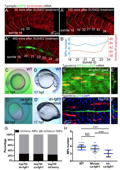
Controls of global and selective FGF perturbations, related to Figure 4 (A-A’’) Time lapse of somite segmentation and MPs differentiation under SU5402 treatment at 60μM. Embryo was treated with SU5402 at 19-somite stage and then mounted for live imaging at 20-somite stage (A) abnormally large somite appeared at 24th somite after 4-5 rounds of somite formation after treatment of SU5402 (A’). MPs are identified at 460 mins after somite segmentation by Eng2a:eGFP (A’’). (B) Graphic representation of MPs number and somite AP length from somite 19 to somite 24 in (A’’). (C and C’) Dorsalisation phenotypes are observed at 10 hpf after injection of cafgfr1 mRNA at one cell stage. (D and D’) Loss of trunk and tail are observed at 17 hpf after injection of dnfgfr1 mRNA into embryos at one cell stage. (E and F) Controls of mosaic FGF perturbations driven by smyhc1:gal4;UAS:mCherry (E) or hsp70l:mCherry (F) respectively. (E’ and F’) Reconstructed transverse view of (E and F) with dorsal to the top and lateral to the left. (G) Fraction of mCherry positive MPs among mCherry positive slow muscles in control group (42/181), FGF inhibited group (38/143) and FGF over-activated group (35/137). (H) Distribution of the number of MPs per muscle segment in wild type embryos (nSomites=55), embryos under mosaic over-activation of FGF signalling (restricted in the fast muscles instead of slow muscles in the corresponding muscle segments) (nSomites=32) and embryos under global over-activation of FGF signalling (nSomites=40). NSp > 0.05 , ***p < 0.001, Student’s t test. |
|
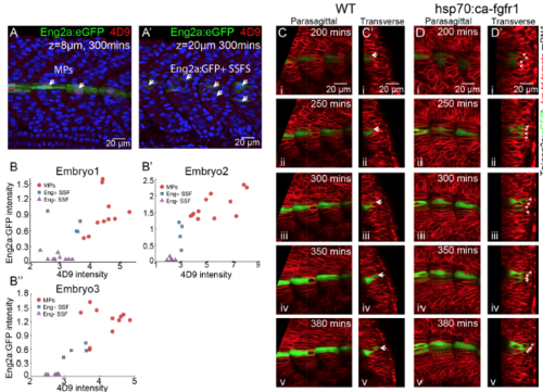
Quantification of Eng expression throughout myogenesis, related to Figure 6 (A and A’) Co-staining of anti-engrailed antibody 4D9 and eng2a:GFP. White short arrows label MPs and eng2a:GFP+ SSFs in (A) and (A’) at different z-plane respectively. Images are taken at around 5 hours later after segmentation of corresponding muscle segments (segments 18-21). (B-B’’) Antiengrailed antibody intensity versus expression level of eng2a:GFP from three embryos among MPs (red circles), eng2a:GFP+ SSFs (blue rectangles) and eng2a:GFP- SSFs(purple triangles). (C and D) Time lapse of MPs differentiation with migrating eng2a:GFP+ SSFs in WT embryos (C) and embryos under heat shock of hsp70l:ca-fgfr1 (D) from 200mins after segmentation to 380mins after segmentation (i-v). (C’ and D’) Transverse view of (C and D) with dorsal to the top and medial to the left. White short arrows label eng2a:GFP+ SSFs. Images are taken at muscle segments 18-21. |
|
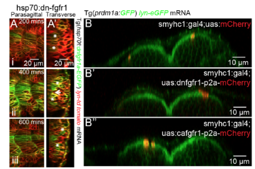
SSF migration under global or local FGFR perturbation, related to Figure 6 (A) Time lapse of slow muscle migration under heat shock of hs:dnfgfr1-GFP. (A’) reconstructed transverse view from (A). White asterisks label the migrating SSFs. Images are taken at muscle segments 18-21. (B) Lateral migration remains intact under mosaic FGF perturbations in slow muscles driven by smyhc1:gal4;UAS:dnfgfr1-p2a-mCherry (B’) and smyhc1:gal4;UAS:cafgfr1-p2a-mCherry (B’’) compared with smyhc1:gal4;UAS:mCherry as a control (B). Lateral to the top and dorsal to the right. Images are taken at muscle segments 14-16 at 30hpf. |
|
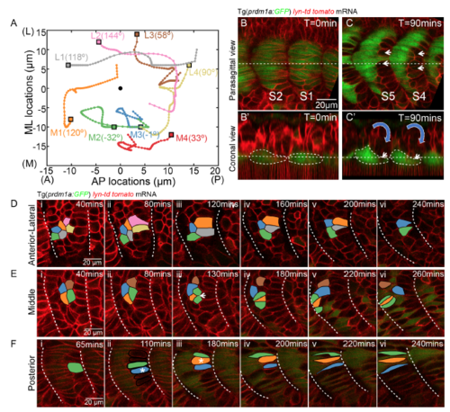
The apparent somite rotation is underpinned by the sequential cell shape changes and muscle elongation, related to Figure 5 and 7 (A) Cell tracking of 8 lateral somitic cells at the coronal plane of (B’) from stage S1 to 8 hours later after the completion of the primary myogenesis. The tracks are displayed with lateral to the top and anterior to the left. The initial positions of the cells are labelled with rectangles with specific colour to the track of each cell. Four relative medial cells are denoted as cell M1, M2, M3 and M4. The other four relative lateral cells are denoted as cell L1, L2, L3 and L4. The black circle denotes the centre of the somite. The angle of rotation of each individual cell relative to the somite centre is labelled in the figure. (B-C) parasagittal (B and C) and coronal (B’ and C’) planes of somite at stage of S2 and S1 (B and B’) and 90 mins later (C and C’). The coronal planes are taken at the positions of the dash lines in the parasagittal planes. Slow muscles are labelled with Prdm1a:GFP. White short arrows denote the posterior fast muscle progenitors that move medially. White dash lines label the contours of slow muscles in (B’ and C’). The blue arrows indicate the direction of the initial apparent somite rotation, prior to slow muscle migration. (D-F) Cell tracking of neighboring lateral somitic cells at distinct locations. (D) Cells located at the lateral surface of the somite. (E) Fast muscle progenitors located at the middle of the somite. (F) Fast muscle progenitors located at the posterior of the somite. White arrow in E (iii) denotes a cell division. White asterisks in F(ii) and F(iii) denote the somitic cells moving medially from the lateral somite. |
|
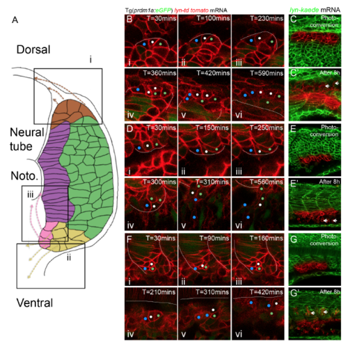
Niches of progenitor cells with non-muscle cell fates and the corresponding migratory paths, related to Figure 5 and 7 (A) Schematic diagram of niches of progenitor cells with non-muscle cell fates and corresponding migratory routes. Three niches revealed in this study locate at dorsal margin (i), lateral ventral margin (ii) and medial ventral margin (iii) of somite. (B-G’) Cell tracking reveals the niches and corresponding migratory routes. (B-C) Progenitor cells stemmed from dorsal margin (i) migrate dorsally and move into the interface between myotome and neural tube. (D-E) Progenitor cells stemmed from lateral ventral margin (ii) migrate ventrally. (F-G) Progenitor cells stemmed from medial ventral margin (iii) migrate to the interface between notochord and myotome. (B, D, F) Cell tracking based on time-lapse imaging. White lines denote to the boundary of myotome. (C, E, G) Cell tracking based on photo-conversion of Kaede at the dorsal and ventral margin. White short arrows label the corresponding non-muscle progenitors at 8 hours after photo-conversion. |
Reprinted from Developmental Cell, 46, Yin, J., Lee, R., Ono, Y., Ingham, P.W., Saunders, T.E., Spatiotemporal Coordination of FGF and Shh Signaling Underlies the Specification of Myoblasts in the Zebrafish Embryo, 735-750.e4, Copyright (2018) with permission from Elsevier. Full text @ Dev. Cell

