
- Title
-
OptoPi: An open source flexible platform for the analysis of small animal behaviour
- Authors
- Cano-Ferrer, X., Roberts, R.J.V., French, A.S., de Folter, J., Gong, H., Nightingale, L., Strange, A., Imbert, A., Prieto-Godino, L.L.
- Source
- Full text @ HardwareX

Fly arena design. a. Mechanical assembly of OptoPi using CAD software on the right. The stimulation and illumination platforms that surround the arena move freely and independently. Fully assembled arena on the left with the Raspberry Pi HQ camera visible in the centre. b. The Raspberry Pi both controls the camera, which records the experiment, and communicates via serial port with the Arduino Mega 2560. The Arduino Mega 2560 has its own shield to allow the researcher to control the source, position and intensity of light as well as the camera position. c. Examples of different lighting configurations. Ambient lighting works best for dark animals such as adult flies and larvae zebrafish when no optogenetic manipulation is required. For optogenetic manipulation and transparent animals such as fly larvae, IR lighting is preferred. |
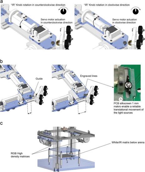
Movements that allow the customization of the device. a. Rotational movement of the infrared light sources are adjusted by rotating the potentiometer. b. The distance from all the light sources (RGB and IR) can be manually adjusted by untightening the M6 screws and sliding the light source platform forwards and backwards. c. Position of the RGB orientable matrices on the top platform and the arena underneath illumination. |
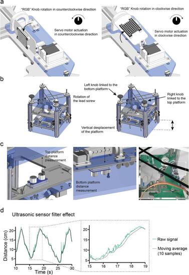
Customisation of light illumination. a. Rotational movement of the RGB matrices actuated by the analogue signal from the PCB potentiometer. b. The vertical position of the light source platforms (both IR and RGB) can be changed independently by rotating the two separate lead screws/ pulley systems. c. The ultrasonic sensors face the roof and the base of the OptoPi structure to measure the distance from each platform to its closest surface. These sensors determine the distance between the illumination platform and the OptoPi bottom and the distance between the stimulation platform and the OptoPi top. d. The moving average filter applied to the ultrasonic sensor signal results in less signal fluctuation making it easier for the user to read. |

Optogenetic module characterization. a. Visible light spectrum of the RGB matrices measured with the Thorlabs CCS200/M compact spectrometer with the CCSB1 cosine corrector b. Irradiance measured on the setup using a platform with a calibrated Thorlabs S120VC photodiode connected to a PM100D compact power meter console. |
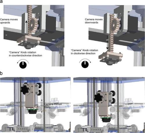
Camera vertical movement. a. The Camera knob actuates the servo motor of the camera translational stage moving the camera up or down and helping the user to select the right imaging distance and the right field of view. b. Manual camera stage adjustment process by tightening or untightening the thumb screw. |

OptoPi components to 3D print. a. With the electromechanical camera stage. b. With the manual camera stage. |
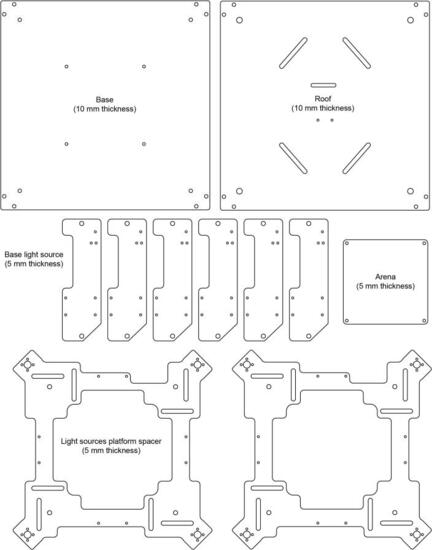
OptoPi components to laser cut. |
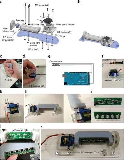
Infrared LED array assembly. a. Exploded view of the illumination infrared LED arrays. b. Assembled view of the illumination infrared LED arrays (Supplementary video 5). c. LED linear array holder inserted into the bearing. d. Servo motor attached to holder with two M2 screws. e. SG90s servo motor connection for its calibration. f. Position of the servo’s arm required for the calibration. g. Two M2 screws are placed on the servo lever after drilling two holes to increase their diameter. h. Assembly completed and detail of the two M2 screws threaded into the LED linear array holder part. i. Infrared LED soldered on the LED array PCB. 68 Ω resistors are soldered onto the other side of the PCB which is attached with four M2 screws threaded on the plastic. j. The PCB is attached with 4 M2 screws on the 3D printed part. The LEDs are inserted into five holes by pushing them through. k. The assembly is completed by attaching it on the base light source part with seven M3 screws and their respective nuts. |
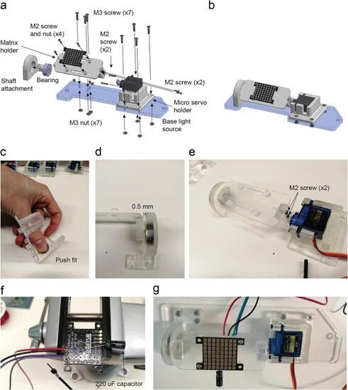
RGB matrix holder assembly. a. Exploded view of the RGB matrix holder. b. Assembled view of the RGB matrix holder (Supplementary video 6). c. The shaft of the matrix holder fits on the bearing by push fit. d. Assembled RGB matrix holder with the detail in the space between the bearing and the 3D printed part to avoid friction. e. Assembled RGB matrix with two M2 screws. f. Detail in the wires soldered on the RGB grid pads as well as the 220 µF capacitor that comes with the grid. g. The assembly is completed by attaching it onto the base light source part with seven M3 screws and their respective nuts. |
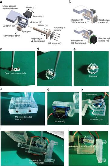
Electromechanical camera linear stage assembly. a. Exploded view. b. Assembled view of both Raspberry Pi camera versions (V2 and HQ) 3D printed holders (Supplementary video 7). c. The servo motor arm is shortened by cutting both sides at the level of the third hole. Then the servo motor screws are screwed in the second hole on each side of the servo motor. d. The arm is placed over the spur gear with the holes coincident. e. The servo arm and the spur gear are attached with the screws. f. Two M3 threaded inserts are inserted by applying pressure before curing the resin. g. The servo motor is attached using two M2 screws with M2 nuts. h. Detail of the M2 screws on the front view of the assembly. i. Spur gear assembly, the rack is placed in the channel and then the spur gear is attached making the teeth coincident and keeping the maximum travel range. j. The servo motor screw holds the spur gear as a final step. |
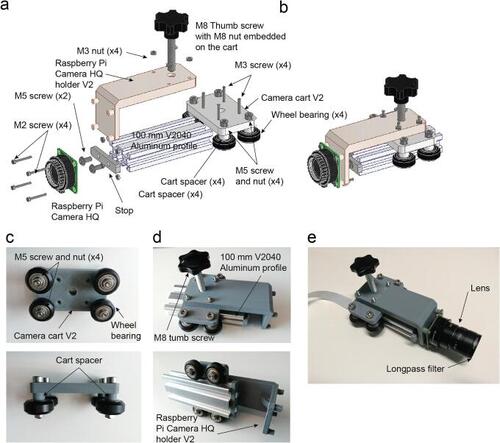
Mechanical camera linear stage assembly. a. Exploded view. b. Assembled view. c. Camera cart assembly. d. Linear rail assembly. e. Camera mounted on the stage. |
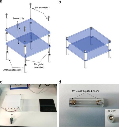
Arena assembly. a. Exploded view. b. Assembled view (Supplementary video 8). c. Different laser cut arena sheets using materials with different opacities. d. Lateral view of the spacer with threaded inserts and top view of the spacer. |
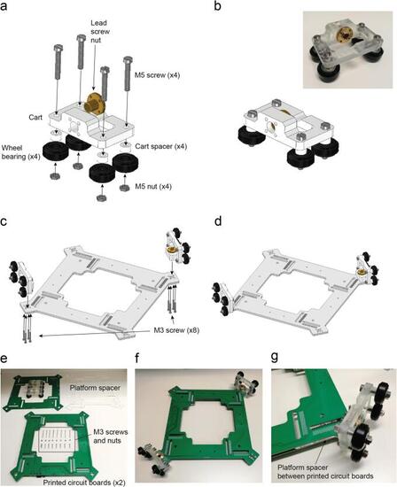
Cart assembly. a. Exploded view. b. Assembled view (Supplementary video 9). Platform assembly. c. Exploded view of the platform assembly. d. Platform assembled with both carts (Supplementary video 10). e. Materials needed to assemble the carts and the platform, Long M3 screws (40 mm) are needed to hold the nut in place. f. Assembled platform with two carts. g. Detail of the platform spacer laser cut in PMMA between two printed circuit boards. |
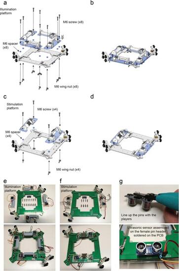
Platform assembly. With IR light sources. a. Exploded view. b. Assembled view (Supplementary video 11). Platform with RGB light sources assembly. c. Exploded view. d. Assembled view (Supplementary video 12). e. IR light sources assembled with the platform. f. RGB light sources assembled with the platform. g. Ultrasonic sensor assembly. |
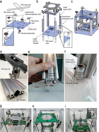
Structure assembly. a. Belt system assembly. b. Assembly of aluminium extrusions 2040, lead screws, arena and both illumination platforms. c. Device assembled (Supplementary video 14, 15, 16). Aluminium extrusions and lead screw coupler details. d. Tap tool M5 size and M5 treads after the process. e. The aluminium 2040 v-slot extrusions are attached with M5 screws to the base after threading the holes they have on both sides. f. The lead screw coupler is held by a M5 screw placed through the base. Assembly of the main structure. g. Illumination platform introduced by the top. h. Stimulation platform introduced by the top. i. Roof installation using M5 screws. |

Timing belts assembly. a. First pair of pulleys. b. Second pair of pulleys. c. Manual adjusters. d. Belt tensioners. |

Control board shield soldering. a. Components required for soldering the control board. b. Control board with its components soldered. c. Platform power supply cables soldering. d. Stimulation platform with soldered components. e. Illumination platform with soldered components. f. Detail of the cable connections and colour codes. g. The phone camera can be used to evaluate if the IR LED are on when we apply power (5 V DC). |
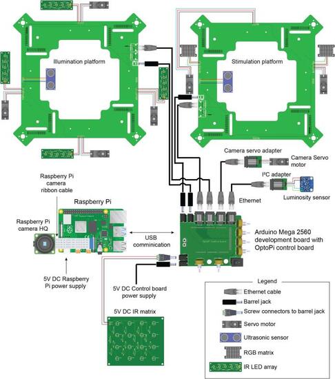
Electrical connections. The wiring required for all the actuators, sensors and illumination with the main control board. |
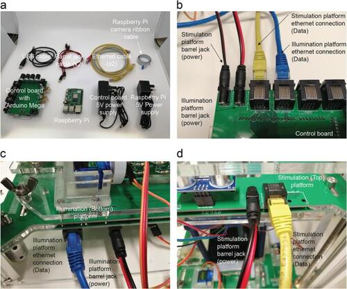
Main connections of the control board. a. Boards and wires required for the final installation and wiring of the OptoPi. b. Data and power connections on the control board. c. Connections on the illumination platform. d. Connections on the stimulation platform. |

Automated functions. a. Ramp profile of light intensity, created by increments of one byte spaced 0.1 s. This pattern is generated by the automated function intensity_ramp(). b. The same function called with 0.2 s interval. c. ON/OFF cycles generated with both RGB matrices with a period of time of 0.1 s between ON and OFF states and an initial time of 10 s in off position. This pattern is generated by the automated function blinking. d. The blinking function using a delay of 0.2 s. |

Experimental characterisation of the illumination and recording modules. a. Example |
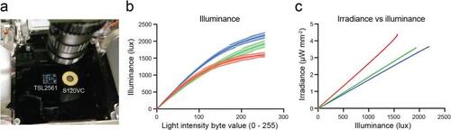
Technical characterisation of the optogenetic module. a. Irradiance characterization setup, the TSL2561 luminosity sensor (left) and the Thorlabs S120VC (Right) on the calibration arena. b. Illuminance functions obtained with two TSL2561 modules (Error bars correspond to the standard deviation). c. The calibration functions obtained comparing illuminance and irradiance functions red (633 nm), green (521 nm) and blue (465 nm) lights. (For interpretation of the references to colour in this figure legend, the reader is referred to the web version of this article.) |

Time precision testing. a. Clock drift between the Raspberry Pi and the Arduino Mega 2560. b. Schematics of connections to connect GPIO 20 and 21 from the Raspberry Pi with the Arduino Digital Pins 20 and 21 (SDA and SCL) which have interrupt capability. c. Time elapsed between the change of the GPIO pin state of the Raspberry Pi and the change of state on the output digital pin of the Arduino, that changes with the interrupt routine. d. Time elapsed between the change of the GPIO pin state of the Raspberry Pi and the change of state on the output digital pin of the Arduino, that changes with the interrupt routine but in this case sending the command to actuate both RGB matrices. |

Experimental characterisation of the optogenetic module. Example |