
|
Fig. 8
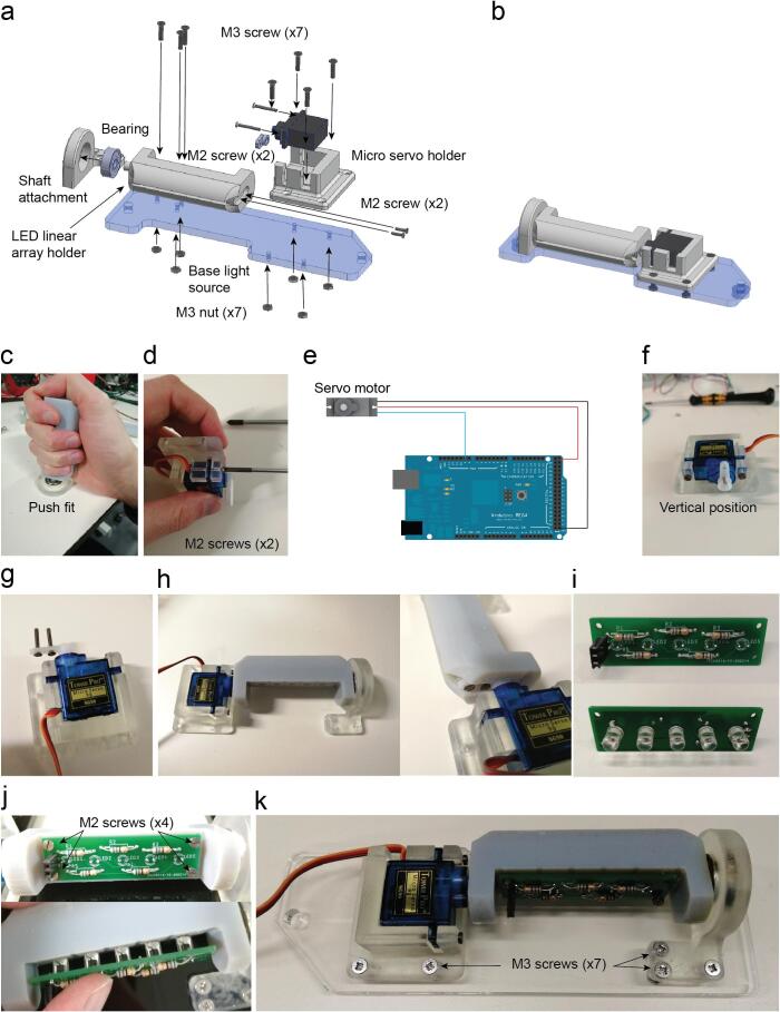
Infrared LED array assembly. a. Exploded view of the illumination infrared LED arrays. b. Assembled view of the illumination infrared LED arrays (Supplementary video 5). c. LED linear array holder inserted into the bearing. d. Servo motor attached to holder with two M2 screws. e. SG90s servo motor connection for its calibration. f. Position of the servo’s arm required for the calibration. g. Two M2 screws are placed on the servo lever after drilling two holes to increase their diameter. h. Assembly completed and detail of the two M2 screws threaded into the LED linear array holder part. i. Infrared LED soldered on the LED array PCB. 68 Ω resistors are soldered onto the other side of the PCB which is attached with four M2 screws threaded on the plastic. j. The PCB is attached with 4 M2 screws on the 3D printed part. The LEDs are inserted into five holes by pushing them through. k. The assembly is completed by attaching it on the base light source part with seven M3 screws and their respective nuts.