
|
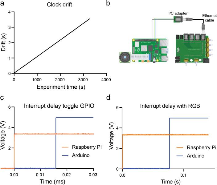
Fig. 23
Time precision testing. a. Clock drift between the Raspberry Pi and the Arduino Mega 2560. b. Schematics of connections to connect GPIO 20 and 21 from the Raspberry Pi with the Arduino Digital Pins 20 and 21 (SDA and SCL) which have interrupt capability. c. Time elapsed between the change of the GPIO pin state of the Raspberry Pi and the change of state on the output digital pin of the Arduino, that changes with the interrupt routine. d. Time elapsed between the change of the GPIO pin state of the Raspberry Pi and the change of state on the output digital pin of the Arduino, that changes with the interrupt routine but in this case sending the command to actuate both RGB matrices.