
|
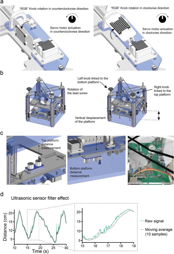
Fig. 3
Customisation of light illumination. a. Rotational movement of the RGB matrices actuated by the analogue signal from the PCB potentiometer. b. The vertical position of the light source platforms (both IR and RGB) can be changed independently by rotating the two separate lead screws/ pulley systems. c. The ultrasonic sensors face the roof and the base of the OptoPi structure to measure the distance from each platform to its closest surface. These sensors determine the distance between the illumination platform and the OptoPi bottom and the distance between the stimulation platform and the OptoPi top. d. The moving average filter applied to the ultrasonic sensor signal results in less signal fluctuation making it easier for the user to read.