
Image
|
Figure Caption
Fig. 9
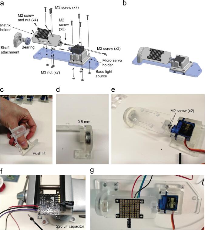
RGB matrix holder assembly. a. Exploded view of the RGB matrix holder. b. Assembled view of the RGB matrix holder (Supplementary video 6). c. The shaft of the matrix holder fits on the bearing by push fit. d. Assembled RGB matrix holder with the detail in the space between the bearing and the 3D printed part to avoid friction. e. Assembled RGB matrix with two M2 screws. f. Detail in the wires soldered on the RGB grid pads as well as the 220 µF capacitor that comes with the grid. g. The assembly is completed by attaching it onto the base light source part with seven M3 screws and their respective nuts.
Acknowledgments
This image is the copyrighted work of the attributed author or publisher, and
ZFIN has permission only to display this image to its users.
Additional permissions should be obtained from the applicable author or publisher of the image.
Full text @ HardwareX