FIGURE

Figure 8.

ID
ZDB-FIG-200225-21
Publication
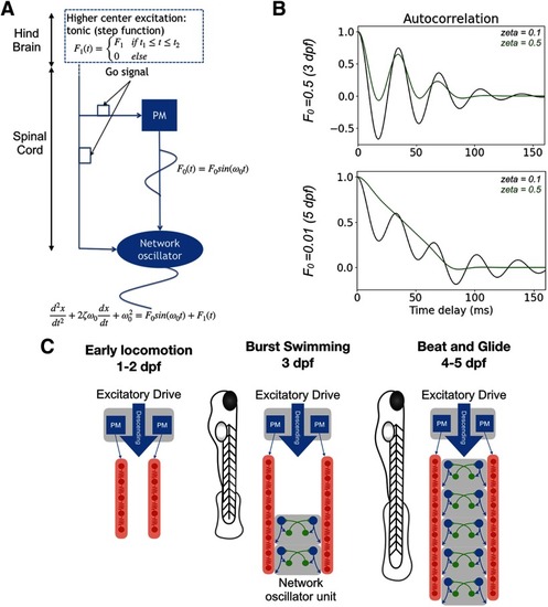
Roussel et al., 2020 - Spatiotemporal transition in the role of synaptic inhibition to the tail beat rhythm of developing larval zebrafish
Other Figures
All Figure Page
Back to All Figure Page
Figure 8.

Coupled oscillator model of architectural change from a pacemaker to a network oscillator-based spinal locomotor circuits of developing zebrafish. A, Schematic of coupled oscillators model. Two coupled oscillators: a harmonic oscillator representing a pacemaker (PM) kernel and a damped oscillator representing a half-center network oscillator. The coupling coefficient F0 represents either the developmental stage or the presence (or absence) of gap-junctions. The damping coefficient models the application or absence of strychnine. The output of the network is read at the output of the half-center. B, Autocorrelation analysis of model output. C, Schematics of the development of spinal locomotor circuits from 3 to 5 dpf. Before 3 dpf, a kernel of IC drives, via gap junctions, two contralateral chains of electrically coupled MNs distributed along the body. Reciprocal inhibition between both sides, which is not illustrated, exists but is not responsible for rhythm generation. After 3 dpf, network oscillators are assembled, first at the caudal end of the spinal cord and then across the length of the spinal cord.

Expression Data

Expression Detail
Antibody Labeling
Phenotype Data

Phenotype Detail
Acknowledgments
This image is the copyrighted work of the attributed author or publisher, and ZFIN has permission only to display this image to its users. Additional permissions should be obtained from the applicable author or publisher of the image. Full text @ eNeuro