
Figure 1
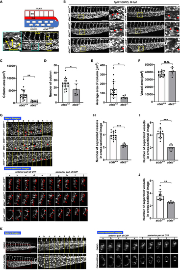
Abnormal caudal vein plexus (CVP) structure in atxb mutant embryos (A) Schematic diagram of blood vessels in the caudal region of the zebrafish embryo. DLAV, dorsal longitudinal anastomotic vessel; ISV, intersegmental vessel; CA, caudal aorta; dCVP, dorsal part of CVP; vCVP, ventral part of CVP. (B) Projection view of confocal z stack images of CVP from the lateral side of wild-type (atxa+/+/atxb+/+), atxb heterozygous (atxa+/+/atxb+/−) and homozygous (atxa+/+/atxb−/−), atxa homozygous (atxa−/−/atxb+/+), atxa homozygous atxb heterozygous (atxa−/−/atxb+/−) and atxa/atxb double-homozygous (atxa−/−/atxb−/−) mutant embryos at 36 hpf. Enlarged images of the area surrounded by squares are positioned on the right side. Arrowheads show the column structure formed between vessels. Scale bar, 100 μm. (C–F) Quantitative evaluation of CVP’s morphology from confocal images from the lateral side. Ten somites from the end of the yolk extension were evaluated. Data were shown as mean with SD of sixteen atxb+/+ and six atxb−/− embryos. p value was calculated by the student’s t test (∗p < 0.05; ∗∗p < 0.01; n.s., no significance). (C) The total area of columns in the ten somites was quantified by Zen 2 (blue edition) software and shown. (D) The total number of columns present across the ten somites. (E) The average area of columns (Total area of columns (C) divided by the number of columns (D)). (F) Total vessel area. The EGFP-positive area was quantified as a vessel area. (G) The cross-sectional single-plane images of CA, dCVP and vCVP from wild-type (atxb+/+/atxb+/+), ATXa KO (atxa−/−/atxb+/+) and ATXb KO (atxb+/+/atxb−/−) embryos at the positions indicated by yellow lines in the upper lateral view are shown in the lower side. Ten somites from the end of the yolk extension were analyzed. Somites a to e and somites f to j were defined as anterior and posterior somites, respectively. Arrowheads indicate the column structures in the lateral images. Arrows, hollow arrowheads and hollow arrows in the cross-sectional images indicate the CA, dCVP and vCVP, respectively. Note that in atxb−/− embryos CA and dCVP were not separated in the posterior part. Scale bar, 100 μm. (H–J) Quantitative evaluation of CVP’s morphology from the cross-sectional images. Data were shown as mean with SD of sixteen atxb+/+ and six atxb−/− embryos. p value was calculated by the student’s t test (∗∗p < 0.01; ∗∗∗p < 0.001). The graphs show the average number of separated vessels in the cross-sectional images from ten somites (somites a to j, H), five anterior somites (somites a to e, I), and five posterior somites (somites f to j, J). (K) Projection views of confocal z stack images from lateral side and cross-sectional images of CVP at 36 hpf. Wild-type embryos were treated with ATX inhibitor, ONO-8430506, from 25 to 36 hpf. Schematic diagrams of the protocol are also shown in the upper side. Scale bar, 100 μm. See also Figures S1, S5, and S6, Videos S1 and S2. |