- Title
-
Haemodynamics-driven developmental pruning of brain vasculature in zebrafish
- Authors
- Chen, Q., Jiang, L., Li, C., Hu, D., Bu, J.W., Cai, D., and Du, J.L.
- Source
- Full text @ PLoS Biol.
|
Structure changes of zebrafish midbrain vasculature during development. (A) Projected confocal images of a 3-dpf Tg(kdrl:eGFP,HuC:gal4-uas-mCherry) zebrafish larva showing the brain blood vasculature (green) and neural tissue (red, bottom). The dashed lines delineate the midbrain position. C, caudal; L, lateral; E, eye; F, forebrain; H, hindbrain; M, midbrain. Dorsal view, caudal is up. The same orientation is used for images and centerlines of whole-midbrain vasculature in all of the following figures. Scale, 100 μm. (B) 3-D reconstruction of the basal communicating artery (BCA, yellow), midbrain vasculature (white), and choroidal vascular plexus (CVP, blue) in the brain shown in (A). Red dots represent the branch points between vessel segments in the midbrain. (C–G) Developmental expansion and simplification of the midbrain vasculature. The data were obtained from eight larvae with each imaged at 2.0, 3.0, 4.0, and 7.5 dpf. (C) Representative midbrain vasculature centerlines of a larva at 2.0 (top), 4.0 (middle), and 7.5 dpf (bottom). Red, orange, yellow, green, cyan, and blue mark vessel segments with the 1st–6th Strahler order, respectively. The white lines indicate internal vessel loops, and the white dots represent branch points between the CVP and midbrain vessel segments. (D–G) Summary of developmental changes in the total vessel length (D), segment number (E), weighted average segment Strahler order (F), and internal loop number (G) of the midbrain vasculature. * p<0.05; ** p<0.01; *** p<0.001 (paired Student′s t test). Error bars, ± SEM. |
|
Occurrence of vessel pruning in the midbrain vasculature during development. (A) Projected confocal image of a left midbrain vasculature in a 3-dpf Tg(kdrl:eGFP) larva. (B) Serial images showing that a vessel segment (arrow) underwent pruning in the midbrain vasculature shown in (A, square). Time, hour:minute. Scales, 25 μm in (A) and 10 μm in (B). (C) Temporal distribution of vessel pruning events observed from eight larvae at each data point. (D and E) An example (D) and summary (E) of data showing that vessel segments formed at 2-dpf underwent extensive pruning during 2.0–7.0 dpf. The data in (E) were obtained from six larvae. (D) Centerline of a 2-dpf midbrain vasculature in which red and blue mark segments were pruned or unpruned during 2.0–7.0 dpf, respectively. The black dots represent branch points between the CVP and midbrain vessel segments. (F and G) Local structural features of pruned vessel segments. (F) Percentages of pruned segments that did not link to the CVP and were located in H-type (87/107) or O-type (19/107) of vascular microcircuits or directly linked to the CVP (1/107). The data were obtained from 18 larvae. Inset, schematic of H-type and O-type of vascular microcircuits. The dashed arrows in the inset indicate the direction of blood flow, and the red and blue lines represent pruned and unpruned vessel segments, respectively. (G) Percentage of pruned segments that were located in internal vessel loop. Error bars, ± SEM. |
|
Changes in blood flow trigger vessel pruning. (A–G) Changes in blood flow before and during vessel pruning. (A–C) Data obtained from the same vessel segments. (A) Representative of simultaneous serial imaging and axial line scanning of midbrain vessels in a 2-dpf Tg(kdrl:eGFP,PU.1:gal4-uas-GFP) larva. Red and blue lines in the first panel indicate the site where axial line scanning was performed on a pruned (red arrow) and its adjacent unpruned segments, respectively. The numbers on the top of each panel represent the blood flow velocity and segment diameter of the pruned vessel segment. The white dashed arrows indicate blood flow direction. White signals in vessels were originated from moving blood cells that expressed GFP. The dashed square in the first panel marks the position from which blood flow is shown in Video S5. (B) Example showing changes with time of the blood flow velocity (filled circle) and diameter (open circle) of pruned (red) and adjacent unpruned (blue) segments before and during vessel pruning. The arrow and arrowhead mark the time point when the blood flow velocity showed an irreversible drop or the segment exhibited an obvious reduction in diameter, respectively. (C) Representative of kymographs showing bi-directional flow in the pruned segment (right) and uni-directional flow in an adjacent unpruned segment (left). The data were obtained from the pruned (red line) and unpruned (blue line) segments in (A) at the time point of 80 min. Green arrows indicate forward movement of blood cells, and yellow ones (right) indicate reverse flow in the pruned segment. (D and E) Average magnitude (D) and coefficient of variation (E) of flow velocities among different time points in pruned and adjacent unpruned segments before the time when an irreversible drop of flow velocity in pruned segments occurred (as indicated by the shadow region in B). The numbers on the bars represent the numbers of segments examined. (F and G) Normalized average magnitude (F) and coefficient of variation (G) of shear stress among different time points in pruned and adjacent unpruned segments before the time when an irreversible drop of flow velocity in pruned segments occurred (as indicated by the shadow region in B). (H and I) Effects of blood flow manipulation on vessel pruning. (H) Representative of serial imaging showing that the obstruction of blood flow by beads triggered vessel pruning. The beads were loaded several minutes before the time zero via the duct of Cuvier microinjection. The red and blue circles mark the beads that were successful or failed to block blood flow, respectively. The red and blue arrows mark the pruned and unpruned segments, respectively. The yellow arrowheads represent moving blood cells in the vessel segment in which a bead (blue circle) failed to block the blood flow. (I) Effects of norepinephrine bitartrate (NB) treatment at 2.0 dpf for 24 h on the occurrence of vessel pruning per larva. Each symbol represents data obtained from one larva. Scales, 10 μm in (A), 5.89 µm (x-axis) and 143 ms (y-axis) in (C) and 10 μm in (H). * p<0.05; ** p<0.01 (Student′s t test). Error bars, ± SEM. |
|
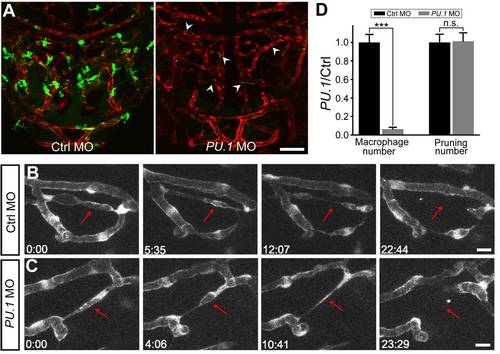
Macrophages are not required for vessel pruning. (A) Projected confocal images showing midbrain vasculature (red) and macrophages (green) in control MO- (left) and PU.1 MO-injected (right) Tg(kdrl:RFP,PU.1:gal4-uas-GFP) larvae at 3 dpf. The green signals in the vessels (arrowheads) were originated from non-specific expression of GFP in blood cells. (B and C) Representative of serial images showing vessel pruning (arrows) in a control MO- (B) and PU.1 MO-injected (C) larvae. (D) Summary of PU.1 knockdown effects on macrophage development and vessel pruning occurrence in the zebrafish midbrain. The data were obtained from 16 larvae in each group. Scales, 50 μm in (A) and 10 μm in (B). n.s., no significance; *** p<0.001 (Student′s t test). Error bars, ± SEM. EXPRESSION / LABELING:
PHENOTYPE:
|
|
Vessel pruning is associated with endothelial cell migration and involves Rac1 activity. (A and B) Representative of tracing of single EC (A) or EC nuclei (B) showing that ECs (arrowheads) in pruned segments (arrows) migrated to adjacent unpruned segments during vessel pruning. The mCherry was mosaically expressed in single ECs of Tg(kdrl:eGFP) embryos (A), and Tg(kdrl:RFP,fli1:nEGFP) larvae were used to trace single EC nuclei (B, yellow). The arrows mark pruned vessel segments, and the arrowheads mark a migrating EC (A) or EC nucleus (B). Scales, 10 µm in (A and B). (C) Mosaic expression of the Raichu Rac1 FRET sensor in vascular endothelial cells of Tg(kdrl:RFP) zebrafish brain. YFP and RFP signals indicate FRET sensor and vascular endothelial cells, respectively. (D) Representative images showing the emission ratio (YFP/CFP) of the same EC expressing Rac1 FRET sensor before and after blood flow reduction induced by 30-min BDM treatment. The intensity of Rac1 FRET signal is color-coded. (E) Summary of data. Data obtained from the same EC are connected by a line. (F) Effect of NSC23766 treatment on the occurrence of vessel pruning per larva. NSC23766 was applied from 2 to 3 dpf and the pruning event was examined between 2 and 3 dpf. Each open symbol represents data obtained from one larva, and the red ones represent the mean values. (G) Working model. In the primitive vasculature (left), some vessel segments exhibit low and unstable blood flow, and ECs located at these segments (pink) undergo lateral migration, leading to vessel pruning. This pruning consequently results in the formation of a simplified vasculature with reduced numbers of internal vessel loop and segment Strahler order (right). Scales, 20 μm in (C) and (D). *** p<0.001 (paired Student′s t test in E and unpaired Student′s t test in F). Error bars, ± SEM. |
|
Midbrain vasculature at 1.5 dpf. (A) Projected confocal image of a 1.5-dpf Tg(kdrl:eGFP) larva showing that some angiogenic sprouts (green arrows) were observed in the midbrain. Inset 1, filopodium-like sprout; Insets 2 and 3, sprouts with an expanded tip. Red and green arrows point to sprouts originated from the choroidal vascular plexus (CVP) or midbrain vasculature, respectively. The dashed square delineates the midbrain position. Scale, 50 μm. (B) 3-D reconstruction of the midbrain vasculature shown in (A). Yellow, basal communicating artery (BCA); white, midbrain vessels; blue, CVP. |
|
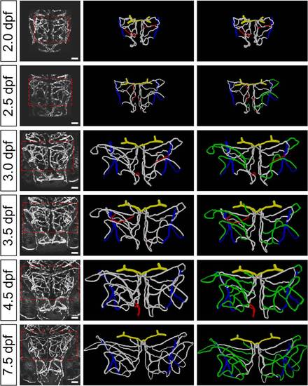
Developmental expansion of midbrain vasculature during 2.0 to 7.5 dpf. Projected confocal images (left) and 3-D reconstruction (middle, right) of a larva′s midbrain vasculature imaged at 2.0, 2.5, 3.0, 3.5, 4.5, and 7.5 dpf. The dashed square delineates the midbrain position. The segments that were pruned at the next time point are marked in red (middle). The newly formed segments after 2.0 dpf through angiogenesis are marked in green (right). Yellow, BCA; white, midbrain vasculature; blue, CVP. Scale, 50 μm. |
|
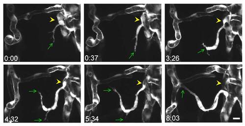
Angiogenesis in the midbrain vasculature. Serial images show the process of vessel ingression from the CVP (yellow arrowheads) into the midbrain. The green arrows point to the tip of angiogenic sprouts. Scale, 10 μm. |
|
Verification of the measurement of blood cell velocity. (A) Projected images of the trunk vasculature in a double transgenic zebrafish Tg(PU.1:gal4-uas-GFP,gata1:DsRed) larva at 4 dpf. Dashed lines delineate the dorsal aorta (DA), posterior cardinal vein (PCV), and intersegmental vessel (ISV). Top, GFP signal; middle, DsRed signal; bottom, merged signal. Scale, 40 µm. (B) Kymographs of blood cells in 4-dpf midbrain vessels by measuring GFP (left) and DsRed (middle) signals. Right, merged. Blue lines mark blood cells expressing both GFP and DsRed. Scales, 5.43 μm (x-axis), 79 ms (y-axis). (C) Comparison of blood flow velocity measured with GFP- or DsRed-expressing blood cells in midbrain vessels. Each point represents the mean velocity of blood flow in one vessel segment, and the data from the same vessel are connected by a line. The mean velocity of each segment was averaged from 100±16 blood cells. The data were obtained from 15 segments in 2 larvae. n.s., no significance (paired Student′s t test). Error bars, ± SEM. |
|
Measurement of plasma flow velocity and its relationship with the occurrence of vessel pruning. (A) Serial images showing a vessel pruning event in the midbrain vasculature of a 2-dpf Tg(kdrl:eGFP) larva, which received microinjection of Fluosphere with green fluorescence (0.5 μm in diameter) into its circulation system. Fluosphere (green) and Dextran (red fluorescence, 10,000 MW) were co-injected into the circulation between –0:43 (hour:minute) and 0:00. The red and blue lines in the first panel indicate the site where axial line scanning was performed on a pruned (red arrow) and its adjacent unpruned segments, respectively. Scale, 20 μm. (B) Fluosphere-based kymographs showing bi-directional plasma flow in the pruned segment (right) and uni-directional flow in its adjacent unpruned segment (left). Scales, 5.43 μm (x-axis), 77.78 ms (y-axis). (C and D) Fluosphere-based calculation of plasma flow velocity (C) and shear stress (D) in pruned (red) and its adjacent unpruned segment (blue). The number on the bar represents the number of vessel segments examined. * p<0.05 (Student′s t test). Error bars, ± SEM. |
|
Effects of heartbeat suppression on vessel pruning. (A–C) Projected images of zebrafish larval midbrain vasculature at 50 hpf. Larvae were treated with normal solution (Ctrl, A), MS222 (tricaine, 0.66 mg/ml; B), or 2,3-butanedione-2-monoxime (20 mM, BDM; C) from 48 hpf and imaged at 50 hpf. (D and E) Projected images of zebrafish larval midbrain vasculature at 2 dpf. Larvae were microinjected with 4 ng control morpholino (Ctrl MO; D) or 4 ng Tnnt2 MO (E). Scale, 50 μm. (F–G) Time-lapse serial imaging showing BDM-induced vessel pruning. The morphology of vessels in the whole midbrain (F) and highlighted area (G) were shown before BDM treatment and after the onset of BDM treatment. BDM was bath-applied during 2–2.5 dpf and imaging was performed during this period. The regressed segments are pointed by the red arrows in the real images or marked in red in the 3-D reconstruction (G). Time, hour:minute. Scales, 50 μm in (F) and 20 μm in (G). PHENOTYPE:
|
|
TUNEL staining of developing zebrafish midbrain. (A) TUNEL staining of DNase I-treated Tg(kdrl:eGFP) zebrafish brain at 3 dpf. DNase I treatment generates strand breaks in the DNA to provide a positive TUNEL reaction. Red, TUNEL signal. The dashed white line delineates the outline of midbrain. (B) Staining of Tg(kdrl:eGFP) zebrafish larva brain without terminal transferase, serving as a negative control. (C and D) Two examples of TUNEL staining of Tg(kdrl:eGFP) zebrafish brain (WT1, WT2) at 3 dpf. Scale, 50 μm. |
|
Effects of down-regulation of VEGFA and Angiopoietin-2 on vessel pruning. (A) Western blotting showing that VEGFA MO reduces VEGFA expression. (B) RT-PCR analysis showing that Angiopoietin-2 (Ang2) splicing MO induces a shift from wild-type (blue asterisk) to mis-spliced transcripts of Ang2 (red asterisk). (C–E) Projected midbrain vasculature images of 3-dpf Tg(kdrl:eGFP) zebrafish larvae injected with control MO (8 ng; C), VEGFA MO (2 ng; D), and Ang2 MO (1 ng; E). (F) Summary of pruning ratio of midbrain vessel segments. The number on the bar in (F) represents the number of zebrafish larvae examined. Scale, 50 μm in (C–E). n.s., no significance; *** p<0.001 (Student′s t test). Error bars, ± SEM. PHENOTYPE:
|
|
Effects of DMOG treatment on vessel pruning. (A) o-Dianisidine staining showing that DMOG treatment increases the amount of blood cells in treated embryos. DMSO (0.2%) or DMOG (0.2 mM) was bath-applied during 2–3 dpf. (B and C) Effect of DMOG treatment on vessel pruning of larval zebrafish midbrain. Projected confocal images showing midbrain vasculature of DMSO- (B) and DMOG-treated (C) zebrafish larvae at 3 dpf. (D) Average number of vessel pruning events occurring between 2 and 3 dpf in single larval zebrafish midbrain. Each small square in (D) represents the data obtained from single larvae. Scale, 50 μm. n.s., no significance (Student′s t test). Error bars, ± SEM. |
|
Method for tracing fate of each vessel segment in the midbrain. (A and B) Projected confocal images (left) and 3-D reconstructions (right) of half midbrain vasculature in a Tg(kdrl:eGFP) zebrafish larvae at 2.5 dpf (A) or 3 dpf (B). Colored balls mark different branch points. The dashed circle marks the site at which a branch point will appear at the next imaging time point. The corresponding movies of the 3-D rotation centerlines are shown in Video S7. Green, newly formed segments; red, pruning segments; blue, CVP. Scale, 50 μm. |


