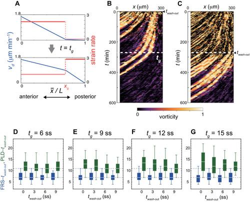
Figure 4—figure supplement 2.
- ID
- ZDB-FIG-210327-102
- Publication
- Uriu et al., 2021 - From local resynchronization to global pattern recovery in the zebrafish segmentation clock
- Other Figures
-
- Figure 1
- Figure 1—figure supplement 1.
- Figure 2—figure supplement 1.
- Figure 2—figure supplement 1.
- Figure 3—figure supplement 1.
- Figure 3—figure supplement 1.
- Figure 3—figure supplement 2.
- Figure 3—figure supplement 3.
- Figure 3—figure supplement 4.
- Figure 3—figure supplement 5.
- Figure 3—figure supplement 6.
- Figure 3—figure supplement 7.
- Figure 3—figure supplement 8.
- Figure 3—figure supplement 9.
- Figure 3—figure supplement 10.
- Figure 3—figure supplement 11.
- Figure 4
- Figure 4—figure supplement 1.
- Figure 4—figure supplement 2.
- Figure 4—figure supplement 3.
- Figure 4—figure supplement 4.
- Figure 4—figure supplement 5.
- Figure 4—figure supplement 6.
- Figure 4—figure supplement 7.
- Figure 4—figure supplement 8.
- All Figure Page
- Back to All Figure Page
|
( |

