- Title
-
Adaptive cell invasion maintains lateral line organ homeostasis in response to environmental changes
- Authors
- Peloggia, J., Münch, D., Meneses-Giles, P., Romero-Carvajal, A., Lush, M.E., Lawson, N.D., McClain, M., Pan, Y.A., Piotrowski, T.
- Source
- Full text @ Dev. Cell
|
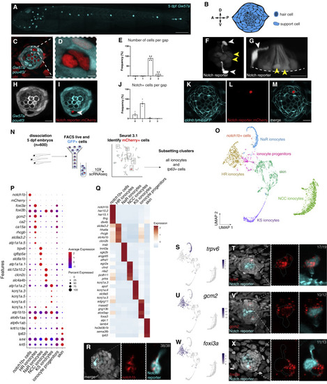
(A) Maximum projection of a 5 dpf Gw57a:EGFP;pou4f3:GFP larva. Scale bar, 300 μm. (B) Schematic of neuromast nuclei, dorsal view. (C) ubi:H2A-mCherry;Gw57a:EGFP;pou4f3:GFP larvae labeling nuclei, support cells and hair cells show a pair of cells that does not express neuromast or hair cell markers, dorsal view. (D) Magnification of (C). (E) Quantification of (C) (n = 4 fish, 36 neuromasts). p < 0.0001 (One-way ANOVA). Error bars = standard error of the mean (SEM). (F) The Notch reporter tp1bglobin:EGFP labels one cell of the pair (white arrowheads) and central support cells (yellow arrowheads). (G) 3D projection of a neuromast with a non-lateral line cell (white arrowhead) and central support cells (yellow arrowheads), lateral view (Video S1). (H and I) (H) Z slice of Gw57a:EGFP;pou4f3:GFP and (I) tp1bglobin:hmgb1:mCherry confirms the Notch+ cell is one of the cells in the gap of (C). (J) Quantification of Notch+ cells per gap (n = 4 fish, 16 gaps).p < 0.0001 (One-way ANOVA). Error bars = SEM. (K–M) cldnb:lyn-GFP;tp1bglobin:mCherry larvae label all neuromasts, skin cells (K), the Notch+ cell (L) and its partner cell. (N) scRNA-seq sorting strategy. (O) UMAP after subsetting ionocytes and tp63+ cells. (P) Dot plot of known ionocyte markers. (Q) Pseudobulk heatmap of cluster markers. (R) notch1b hybridization chain reaction (HCR). (S) Feature plot for trpv6. (T) HCR of trpv6 in the Notch+ cell (n = 6 fish, 12 neuromasts). n numbers = number of Nm ionocyte pairs analyzed. Magnification of the boxed area. (U) Feature plot for gcm2. (V) gcm2 is expressed in both cells in the pair (n = 4 fish, 11 neuromasts). (W) Feature plot of foxi3a. (X) foxi3a is expressed in the Notch− ionocyte (n = 5 fish, 12 neuromasts). All images, except (A) and (G) were blurred. (A), (F), and (G) were non-linear adjusted (gamma). Scale bars, 10 μm, unless otherwise noted. See also Figure S1 and Video S1. |
|
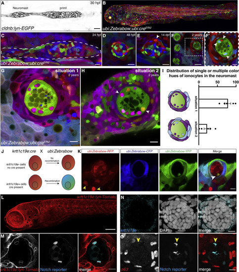
(A) 30 hpf cldnb:lyn-GFP+ lateral line primordium and deposited neuromast. (B) Maximum intensity projection of a 3 dpf ubi:Zebrabow larva recombined during shield stage. (C–E) (C) 24 hpf primordium recombined for 15 min at 4 hpf. Neuromast in (C) is mosaic at 48 hpf (D) and 14 dpf (arrowhead indicates the new cell) (E). (F and F′) Neuromasts in 2-year-old fish recombined between 16–24 hpf have become clonal. Scale bar in (F), 30 μm. (G and H) (G) Z slices of 2-year-old recombined ubi:Zebrabow;ubi:creERt2 fish show Nm ionocyte pairs of the same color hue as skin cells surrounding the neuromast or (H) Nm ionocyte pairs of two different color hues (white arrows) also shared with surrounding skin cells. (I) Quantification of (G and H) (n = 5 fish, 194 neuromasts). Error bars indicate SEM. (J) Overview of lineage tracing experiments with ubi:Zebrabow and krtt1c19e:cre-MYC. (K) A 5 dpf ubi:Zebrabow;krtt1c19e:cre-MYC neuromast shows a pair of recombined cells (white arrowhead) in between red, unrecombined cells. Skin ionocytes differentiate before Cre expression and are not recombined (yellow arrowheads). (L) 5 dpf krtt1c19e:lyn-Tomato larva labels basal keratinocytes. Scale bar, 100 μm. (M) 5 dpf krtt1c19e:lyn-Tomato;tp1bglobin:EGFP neuromast. krtt1c19e channel was gamma adjusted. (N) krtt1c19e HCR and (O) TP63 immunohistochemistry does not label cells in the neuromast (Notch+ ionocytes indicated by red arrowhead). Scale bars, 10 μm, unless stated otherwise. See also Figure S2. |
|
(A) Still images of a time-lapse recording of two Nm ionocyte precursors (colored dots) entering a 3 dpf Et4;Et20;cldnb-lynEGFP neuromast (Video S2). Magnification of boxed area is shown below. Scale bar, 5 μm, images were gamma adjusted. (B) Individual z slices of a time-lapse recording of a Gw57a:EGFP;ubi:H2A-mCherry larva at 3 dpf, with Nm ionocyte precursor cells migrating into the neuromast (right panels, colored dots), creating a gap in EGFP fluorescence (left panels, orange arrowheads, Video S3). Scale bar, 5 μm. (C and D) Tracks of two Nm ionocyte precursor cell pairs in a 2 dpf cldnb:H2A-mCherry larva (Video S4). Red and cyan dots depict the position of the Notch− and the Notch+ cell of each pair at the start (C) and end point of the movie (D). (E and E′) Quantification of the distance from the start position of the cells tracked in (C) and (D) over time. (F) Quantification of the cell speed calculated based on the net distance, as well as the summed distance that Notch+ cells traverse (n = 7 neuromasts, 10 cells). (G) Rose plots displaying the angular position at which Nm ionocyte precursors enter neuromasts of different polarities (primI- and primII, blue and red labeling, respectively) (n = 15 neuromasts, 7 fish). Binomial test revealed no directional bias. (H and I) Angular, final position of Nm ionocytes in primI- and primII-derived 5 dpf neuromasts (H), and their spatial distribution in relation to mantle cell position (I) (n = 55 neuromasts). Binomial analysis showed significant bipolar localization (p < 0.0001) with a slight directional bias toward posterior in primI-derived neuromasts (p = 0.004). (J and J′) Nm ionocyte localization in primI-derived (J) and primII-derived neuromasts at 5 dpf (J′). Images were gamma adjusted. (K) Still images of a time-lapse recording at 3 dpf, depicting protrusions of a Notch+ Nm ionocyte precursor (orange arrowheads) before stabilizing an apical extension (red arrowheads, Video S5). Images were gamma adjusted. Scale bar, 5 μm. (L) Gradual increase in Notch reporter fluorescence (left panel, orange arrowheads; right panel, white arrowheads) as Nm ionocyte precursor cells (left panel, colored dots) re-arrange between neuromast cells (Video S6). (M) Quantification of Notch reporter GFP fluorescence over time, normalized by the average of all the curves up to the 160 min time point. (N–N″) Nm ionocyte frequency (shown as gaps in Gw57a:EGFP;pou4f3:GFP, orange arrowheads) following inhibition of Notch signaling with 50 μM LY411575 for 24 h (n = 14 larvae, 84 neuromasts) between 5 and 6 dpf compared with DMSO controls (n = 12 larvae, 72 neuromasts; Mann-Whitney test, p < 0.0001). (O) Still images of time lapse from a 4 dpf larva (Gw57a:EGFP; ubi:H2A-mCherry) show a pair of Nm ionocyte undergoing cell death after Notch inhibition. (P) Quantification of time lapses assessing Nm ionocyte death after incubation with 50-μM LY411575 (n = 8 larvae, 18 neuromasts) compared with DMSO controls (n = 3 larvae, 5 neuromasts). Scale bars, 10 μm, unless otherwise noted. Dashed black lines in violin plots indicate the median, while dotted black lines indicate quartiles. See also Figure S3 and Videos S2, S3, S4, S5, S6, S7, and S8. EXPRESSION / LABELING:
PHENOTYPE:
|
|
(A) Maximum intensity projection of a neuromast labeled by she:H2A-mCherry;tp1bglobin:EGFP shows nuclei of the neuromast cells in red and three Notch+ Nm ionocytes in cyan. (B) 3D modeling of the SBF-SEM stack of the same neuromast in (A). (C) 3D modeling of the Nm ionocyte pair (white and cyan). (D) Single image of a transverse section of the SBF-SEM shows the apical part of a pair of Nm ionocytes (white square) and neuromast cells (red nuclei). (E) Magnification of white square in (D) showing microvilli (red arrowhead) and the apical crypt of the ionocyte pair exposed to the outside of the neuromast. (F) 3D modeling of the microvilli (red arrowheads) containing crypt of the Notch− cell. (G) A neuromast labeled by she:H2A-mCherry;tp1bglobin:EGFP. (H) Scanning electron micrograph of the same neuromast in (G). (I) Magnification of the region in white square in (H). Red arrowhead depicts an opening in the neuromast cuticular plate that correlates with the position of the Nm ionocyte pair. (J) Lateral view of a 3D projection of a tp1bglobin:EGFP;Myo6b:Lck-mScarlet-I neuromast (Video S11). Nm ionocytes have long apical projections with the apical crypt (white arrowheads) close to the cuticular plate. (K) Model of the neuromast (red) containing a pair of Nm ionocytes (white and cyan). (A) and (G) are non-linear adjusted (gamma). See also Figure S4 and Videos S10 and S11. EXPRESSION / LABELING:
PHENOTYPE:
|
|
(A) Percentage of neuromasts with Notch+ Nm ionocytes at 3 dpf (n = 9 fish, 117 neuromasts), 4 dpf (n = 9 fish, 125 neuromasts), 5 dpf (n = 10 fish, 162 neuromasts), 14 dpf (n = 5 fish, 49 neuromasts) and in 2-year-old adult fish (n = 3 fish, 78 neuromasts, Mann-Whitney test). (B) Average number of Notch+ Nm ionocytes per neuromast at stages quantified in (A), (same n-numbers, Mann-Whitney test). (C) Representative maximum intensity projections of Nm ionocytes (arrowheads) at stages quantified in (A) and (B). (D) Maximum intensity projections of the same ubi:Zebrabow;ubi:creERt2 neuromast at 21 dpf (upper panel) and 28 dpf (lower panel) with newly appeared Nm ionocytes (arrowheads). (E) Nm ionocyte number in larvae incubated in control media (0.5× E2) or different concentrations (MilliQ, n = 11 fish, 154 neuromasts; 0.1× E2, n = 30 fish, 433 neuromasts; 0.5× E2, n = 31 fish, 436 neuromasts; 2.5× E2, n = 31 fish, 449 neuromasts; 5× E2, n = 31 fish, 454 neuromasts; Kruskal-Wallis ANOVA and Dunn’s post hoc test). (F) Representative images of neuromasts and Nm ionocytes (arrowheads) following incubation in E2 media dilutions. (G) Percentage of neuromasts with Nm ionocytes in larvae incubated in different E2 media dilutions (n numbers as in E, Kruskal-Wallis ANOVA and Dunn’s post hoc test). (H) Nm ionocyte frequency in acidic (pH = 4; n = 20 fish, 286 neuromasts), alkaline (pH = 10; n = 20 fish, 291 neuromasts), and neutral E2 media (pH = 7, n = 20 fish, 296 neuromasts; unpaired t test). (I) Percentage of neuromasts with Nm ionocytes following incubation in E2 media of different pH (n numbers as in H, Mann-Whitney test). (J) Representative images of Nm ionocytes (arrowheads) as quantified in (I). (K) Average Nm ionocyte frequency in foxi3a−/− fish (n = 20 fish, 312 neuromasts) and their siblings (n = 42 fish, 637 neuromasts; Mann-Whitney test). (L) Representative maximum projections of Nm ionocytes (arrowheads) in foxi3a−/− fish and their siblings. (M) foxi3a and trpv6 HCR in foxi3a−/− fish (lower panel, n = 21 neuromasts, 4 fish) and their siblings (upper panel, n = 22 neuromasts, 7 fish). Cyan n numbers indicate the number of neuromasts with trpv6+ Nm ionocytes. Magnification of boxed area is shown on the right. (N) gcm2 HCR in foxi3a−/− fish in the Notch reporter background (lower panel, n = 25 neuromasts, 3 fish) and their siblings (upper panel, n = 96 neuromasts, 12 fish). Cyan n numbers indicate the number of neuromasts with gcm2+ Nm ionocytes. Magnification of boxed area is shown on the right. (O) FM1-43+ hair cell numbers in foxi3a−/− fish (n = 15 fish, 30 neuromasts) and their siblings (n = 11 fish, 22 neuromasts). (P) FM1-43 intensity of hair cells in foxi3a−/− fish (n = 9 fish, 18 neuromasts) compared with their siblings (n = 13 fish, 26 neuromasts; unpaired t test). Data are shown as fluorescence intensity/background, normalized to the average of the siblings. (Q) FM1-43 dye uptake by hair cells in foxi3a−/− fish and their siblings, as quantified in (P). Scale bars, 5 μm. All scale bars, 10 μm, unless otherwise noted. Error bars indicate standard deviation. Dashed lines in violin plots indicate the median, dotted lines indicate quartiles. Individual data points in (A, B, E, G, H, I, and K) represent an average of all neuromasts quantified per fish. See also Figure S4. EXPRESSION / LABELING:
PHENOTYPE:
|
Reprinted from Developmental Cell, 56(9), Peloggia, J., Münch, D., Meneses-Giles, P., Romero-Carvajal, A., Lush, M.E., Lawson, N.D., McClain, M., Pan, Y.A., Piotrowski, T., Adaptive cell invasion maintains lateral line organ homeostasis in response to environmental changes, 1296-1312.e7, Copyright (2021) with permission from Elsevier. Full text @ Dev. Cell


