- Title
-
Clarification of mural cell coverage of vascular endothelial cells by live imaging of zebrafish
- Authors
- Ando, K., Fukuhara, S., Izumi, N., Nakajima, H., Fukui, H., Kelsh, R.N., Mochizuki, N.
- Source
- Full text @ Development
|
Generation of Tg zebrafish lines for live imaging of MCs. (A) A schematic structure of the BAC clone (CH1073-606I16) used to generate Tg zebrafish lines for live imaging of MCs. cDNA encoding either EGFP, mCherry or Gal4FF was inserted at the start codon of pdgfrb gene. (B) Confocal stack fluorescence image of trunk vasculature in a 96hpf TgBAC(pdgfrb:Gal4FF);Tg(UAS:GFP);Tg(fli1a:Myr-mCherry) larva. Lateral view, anterior to the left. Merged image of pdgfrb:Gal4FF;UAS:GFP (green) and fli1a:Myr-mCherry (red). (C-F) Confocal images of hindbrain vasculature (C,D), hyaloid vessels (E) and anterior region of dorsal aorta (F) in the TgBAC(pdgfrb:EGFP);Tg(fli1a:Myr-mCherry) larvae at 60hpf (C) and 80hpf (D-F). Dorsal view, anterior to the left. Merged images of pdgfrb:EGFP (green) and fli1a:Myr-mCherry (red). In C, the boxed areas are enlarged to the right. (G) Confocal images of trunk vasculature in a 1mpf TgBAC(pdgfrb:EGFP);Tg(fli1a:Myr-mCherry) juvenile. Cross-sectional views (200µm thick) through the caudal region as depicted in Fig. S1H are shown. Upper left, pdgfrb:EGFP (green); upper center, fli1a:Myr-mCherry (red); upper right, merged image. The boxed areas labeled a and b are enlarged below. (H) Confocal images of blood vessels in the intercostal muscle of a 1mpf TgBAC(pdgfrb:EGFP);Tg(fli1a:Myr-mCherry) juvenile. Pleural tissue as indicated by the box shown in g was cut out and immunostained with anti-α-SMA antibody to visualize VSMCs. The merged image of pdgfrb:EGFP (green) and fli1a:Myr-mCherry (red) is shown on the left (a). The boxed area in a is enlarged to the right: pdgfrb:EGFP (b), fli1a:Myr-mCherry (c), α-SMA (d), merge of pdgfrb:EGFP (green) and fli1a:Myr-mCherry (red) (e) and merge of pdgfrb:EGFP (green), fli1a:Myr-mCherry (red) and α-SMA (blue) (f). (g) Brightfield image of the thorax showing the region where the image shown in a was taken. BA, basilar artery; BCA, basal communicating artery; CCtA, cerebellar central artery; DA, dorsal aorta; LDA, lateral DA; HV, hyaloid vessel; PCS, posterior communicating segment; PHBC, primordial hindbrain channel. Scale bars: 20µm (enlarged images in C and H; D-F); 50µm (B,C); 100µm (G,H). EXPRESSION / LABELING:
|
|
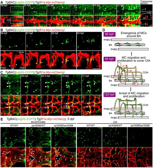
Live imaging of MC coverage in cranial vessels. (A-C) Time-lapse confocal images of the hindbrain vasculature in TgBAC(pdgfrb:EGFP);Tg(fli1a:Myr-mCherry) larvae at 35-42hfp (A), 59-63hpf (B) and 65-71hpf (C). Upper, pdgfrb:EGFP; lower, merged images of pdgfrb:EGFP (green) and fli1a:Myr-mCherry (red). (A) Dorsal view, anterior to the left. The central panels are enlarged and subsequent time-lapse images of the boxed areas in the leftmost column. The transverse sectional views of the areas indicated by dashed lines on the 42hpf image are shown in the rightmost column. Top, pdgfrb:EGFP (green); middle (rightmost column only), fli1a:Myr-mCherry (red); bottom, merged image. Note that the cells located in the vicinity of the BA (arrowheads) gradually emitted strong EGFP signal and tightly contacted ECs. (B) 3D-rendered confocal images of EGFP-positive cells (green) migrating along the CCtAs. Lateral view, dorsal to the top and anterior to the front. Note that EGFP-positive cells located around the BA (arrowheads) dorsally migrated along the CCtAs. (C) Dorsal view, anterior to the left. Arrowheads with numbers indicate individual EGFP-positive cells spreading on the CCtAs. Note that EGFP-positive cells spreading on the CCtA (1 and 2) divided into two daughter cells (1-1/1-2 and 2-1/2-2). (D) Schematic of how CCtAs become covered by MCs. MCs develop around the BA and migrate towards the CCtAs. During their migration, the MCs actively proliferate to cover the CCtAs. (E) Confocal images of hindbrain vasculature of pdgfrb wild-type (WT/WT), heterozygous (sa16389/WT) and homozygous (sa16389/sa16389) larvae in the TgBAC(pdgfrb:EGFP);Tg(fli1a:Myr-mCherry) background at 5dpf. Dorsal view, anterior to the left. The vessels in the cerebral base, such as BCA, PCA and BA (BCA/PCS/BA), and the CtA, are shown in the left and right columns, respectively. Upper, pdgfrb:EGFP; lower, merged images of pdgfrb:EGFP (green) and fli1a:Myr-mCherry (red). Arrowheads indicate MCs emerged around the BCA, PCS and BA. Scale bars: 20µm (transverse sectional image in A); 50µm (A,B,C,E). EXPRESSION / LABELING:
PHENOTYPE:
|
|
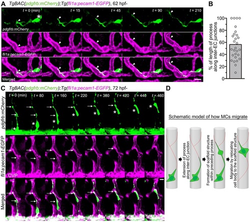
Migration of MCs along inter-EC junctions. (A) Time-lapse confocal images of an MC migrating along the CtA in the hindbrain of a TgBAC(pdgfrb:mCherry);Tg(fli1a:pecam1-EGFP) larva. 3D-rendered confocal images at 62hpf (leftmost column) and their subsequent time-lapse images with the elapsed time (min) at the top right. Top, pdgfrb:mCherry (green); middle, fli1a:pecam1-EGFP (magenta); bottom, merged images. Arrowheads and asterisk indicate the tip of the MC process and the cell body, respectively. Note that the MC extended a process along the Pecam1-EGFP-labeled inter-EC junctions. (B) Alignment of MC processes along inter-EC junctions, as observed in A, expressed as a percentage of the total length (n=28). Bar and circles indicate the average and the values of individual processes, respectively. (C) Time-lapse confocal images of an MC migrating along the CtA, as in A. 3D-rendered confocal images at 72hpf (leftmost column) and their subsequent time-lapse images with the elapsed time (min) at the top right. Note that the MC moved forward by sequentially relocating its cell body (asterisks) to the punctate structures formed within the preceding processes (arrows). CVP, choroidal vascular plexus. (D) Schematic of how MCs migrate along the EC tube to cover the CtA. Red lines indicate the inter-EC junctions, green cells represent MCs. Scale bars: 10µm (A,C). EXPRESSION / LABELING:
|
|
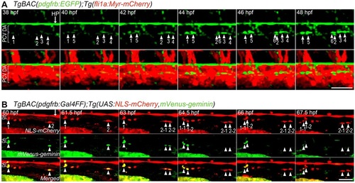
Live imaging of MC coverage of axial vessels in the trunk. (A) Time-lapse confocal images of an axial vessel in the trunk of TgBAC(pdgfrb:EGFP);Tg(fli1a:Myr-mCherry) embryos (38-48hpf). Upper, pdgfrb:EGFP; lower, merged images of pdgfrb:EGFP (green) and fli1a:Myr-mCherry (red). Arrowheads with numbers indicate individual EGFP-positive cells emerging at the ventral part of the DA. Arrow indicates hypochord (HP). (B) Time-lapse confocal images of a trunk axial vessel in TgBAC(pdgfrb:Gal4FF);Tg(UAS:NLS-mCherry,mVenus-geminin) embryo (60-67.5hpf). Top, NLS-mCherry (red); middle, mVenus-geminin (the cells in the S/G2/M phase of the cell cycle) (green); bottom, merged images. Arrowheads with numbers indicate individual mCherry/mVenus double-positive cells located in the ventral part of DA. Note that mCherry/mVenus double-positive cells (1 and 2) divided into two daughter cells (1-1/1-2 and 2-1/2-2), which subsequently lost mVenus fluorescence. Arrow indicates hypochord. Lateral view, anterior to the left. Scale bars: 50µm. |
|
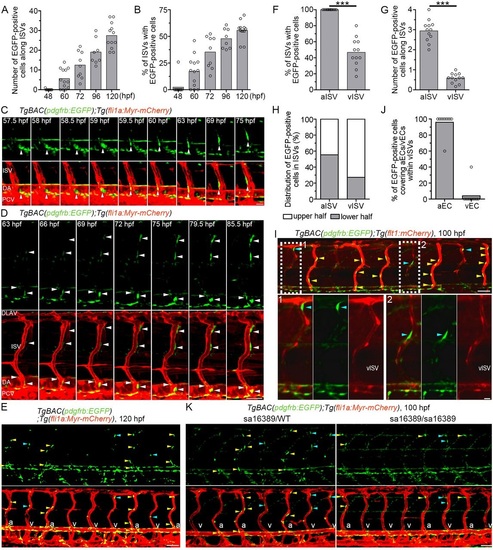
Live imaging of MC coverage of ISVs. (A,B) The number of EGFP-positive cells covering mCherry-labeled ISVs (A) and the percentage of ISVs covered by more than one EGFP-positive cell (B) in the left side of TgBAC(pdgfrb:EGFP);Tg(fli1a:Myr-mCherry) embryos or larvae at the stages indicated below. (ne8). (C) Time-lapse confocal images of the trunk vasculature in a TgBAC(pdgfrb:EGFP);Tg(fli1a:Myr-mCherry) embryo (57.5-75hpf). Upper, pdgfrb:EGFP; lower, merged image of pdgfrb:EGFP (green) and fli1a:Myr-mCherry (red). Arrowheads indicate an EGFP-positive cell that initially located in the ventral part of DA and subsequently migrated towards the ISV. (D) Time-lapse confocal images of the trunk vasculature in a TgBAC(pdgfrb:EGFP);Tg(fli1a:Myr-mCherry) embryo (63-85.5hpf), as in C. Arrowheads indicate EGFP-positive cells covering the ISVs. Note that the cells around the ISVs gradually emitted a stronger EGFP signal. (E) Confocal images of trunk vasculature in a TgBAC(pdgfrb:EGFP);Tg(fli1a:Myr-mCherry) larva at 120hpf. Upper, pdgfrb:EGFP; lower, merged image of pdgfrb:EGFP (green) and fli1a:Myr-mCherry (red). Yellow and blue arrowheads indicate the EGFP-positive cells covering arterial ISVs (aISVs) and those covering venous ISVs (vISVs), respectively. ‘a’ and ‘v’ in the merged image indicate aISVs and vISVs, respectively. (F) Percentage of aISVs/vISVs covered by more than one EGFP-positive cell, as observed in E (n≥12). (G) The number of EGFP-positive cells covering aISVs/vISVs, as observed in E (n≥12). (H) Percentage of EGFP-positive cells covering the upper and lower half of aISVs/vISVs, as observed in E (n=12). (I) Confocal images of trunk vasculature in a TgBAC(pdgfrb:EGFP);Tg(flt1:mCherry) larva at 100hpf. Fluorescence signal derived from flt1:mCherry labels arterial ECs (Bussmann et al., 2010). The merged image of pdgfrb:EGFP (green) and flt1:mCherry (red) is shown at the top. The boxed areas labeled 1 and 2 are enlarged at the bottom, showing the merged image of pdgfrb:EGFP and flt1:mCherry (left), pdgfrb:EGFP (center) and flt1:mCherry (right). Yellow and blue arrowheads indicate the EGFP-positive cells covering aISVs and those covering vISVs, respectively. Note that MCs adhered to the flt1:mCherry-positive arterial ECs within vISVs. (J) Percentage of EGFP-positive cells adhering to arterial ECs (aEC) and those adhering to venous ECs (vECs) within vISVs, as observed in I (n=10). (K) Confocal images of trunk vasculature of the pdgfrb heterozygous (sa16389/WT) and homozygous (sa16389/sa16389) larvae in the TgBAC(pdgfrb:EGFP);Tg(fli1a:Myr-mCherry) background at 100hpf are shown, as in E. In A,B,F,G and J, bars and circles indicate averages and individual values, respectively. ***P<0.001. Lateral view, anterior to the left. DLAV, dorsal longitudinal anastomotic vessel; ISV, intersegmental vessel; DA, dorsal aorta; PCV, posterior cardinal vein; aISV, arterial ISV; vISV, venous ISV. Scale bars: 20µm (C, enlarged images in I); 50µm (D,E,I,K). EXPRESSION / LABELING:
|
|
Lineage tracing for identification of MC origins. (A) Schematic of the protocol used for lineage-tracing analysis. TgBAC(pdgfrb:Gal4FF);Tg(UAS:loxP-mCherry (mC)-loxP-mVenus (mV)) zebrafish (pdgfrb reporter) express mCherry in the pdgfrb-positive cells (top). In the pdgfrb reporter fish crossed with Tg(sox10:Cre) or Tg(tbx6:Cre,myl7:EGFP) line, the sox10-positive neural crest-derived MCs or tbx6-positive mesoderm-derived MCs, respectively, are labeled with mVenus expression because of Cre-mediated excision of mCherry gene flanked by loxP (bottom). (B) Lateral view of a TgBAC(pdgfrb:Gal4FF);Tg(UAS:loxP-mC-loxP-mV);Tg(sox10:Cre) larva at 5dpf. Upper, mVenus; lower, brightfield image. (C) Confocal images of head (left column) and trunk (center and right columns) regions in a TgBAC(pdgfrb:Gal4FF);Tg(UAS:loxP-mC-loxP-mV);Tg(tbx6:Cre,myl7:EGFP) larva at 5dpf. Upper, mVenus; middle, merged images of mVenus (green) and mCherry (red); lower, differential interference contrast (DIC) images. (D) Confocal images of head regions in a 5dpf TgBAC(pdgfrb:Gal4FF);Tg(UAS:loxP-mC-loxP-mV) larva crossed with Tg(sox10:Cre) (left three columns) or Tg(tbx6:Cre,myl7:EGFP) (right three columns) fish lines. Dorsal view, anterior to the left. Images of CCtA, BCA/PCS and HV are shown in the left, center and right columns, respectively. Upper, mVenus; lower, the merged images of mVenus (green) and mCherry (red). Note that mVenus-labeled cells indicate sox10-positive neural crest-derived MCs (left three columns) or tbx6-positive mesoderm-derived MCs (right three columns). Scale bars: 50µm (CCtA, HV); 20µm (BCA/PCS). (E) Confocal images of pharyngeal regions in 5dpf TgBAC(pdgfrb:Gal4FF);Tg(UAS:loxP-mC-loxP-mV);Tg(IF:NLS-mCherry,fli1a:iRFP) larvae crossed with Tg(sox10:Cre) (left three columns) or Tg(tbx6:Cre,myl7:EGFP) (right three columns) fish lines. The larvae expressing iRFP670 under the control of fli1a promoter were identified by intestinal fatty acid binding protein (IF; also known as fabp2) promoter-driven expression of NLS-mCherry in the intestine. Ventral view, anterior to the left. Boxed areas showing hypobranchial artery (HA) (a,c) and aortic arches (AA) (b,d) are enlarged to the right of the original images. Top row, mVenus; second row, mCherry; third row, fli1a:iRFP (iRFP); bottom row, merged images of mVenus (green), mCherry (red) and iRFP (white). Scale bars: 50µm. Asterisks in C and E indicate heart visualized by myl7:EGFP. mC, mCherry; mV, mVenus; i, iris; j, jaw; p, pharyngeal arch. EXPRESSION / LABELING:
|
|
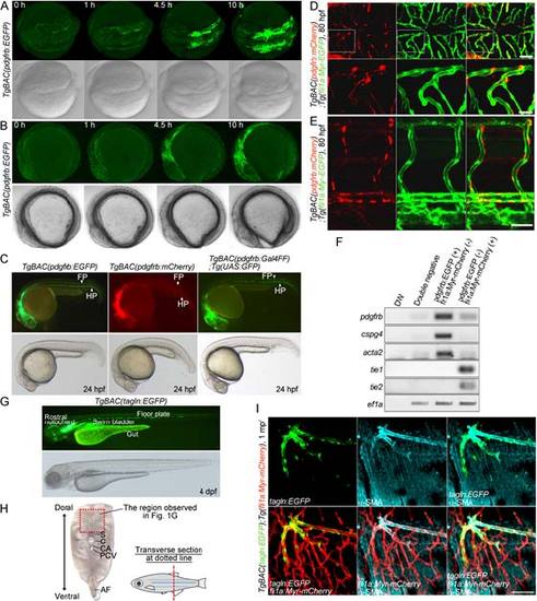
Characterization of TgBAC(pdgfrb:EGFP) and TgBAC(tagln:EGFP) zebrafish lines. (A, B) Time-lapse confocal images of the TgBAC(pdgfrb:EGFP) embryos from 8 somite stage. Dorsal (A) and lateral (B) view images at 8 somite stage (leftmost column) and their subsequent time-lapse images with the elapsed time (h) at the top. Upper, pdgfrb:EGFP; lower, bright field image. (C) Lateral views of TgBAC(pdgfrb:EGFP)(left), TgBAC(pdgfrb:mCherry)(center) and TgBAC(pdgfrb:Gal4FF);Tg(UAS:GFP)(right) zebrafish embryos at 24 hpf. Upper, pdgfrb:EGFP (left),pdgfrb:mCherry(center) and pdgfrb:Gal4FF;UAS:GFP(right); lower, bright field images. FP, floor plate; HP, hypochord. (D, E) Dorsal view of CtAs (D) and lateral view of trunk vessels (E) in the TgBAC(pdgfrb:mCherry);Tg(fli1a:Myr-EGFP) larvae at 80 hpf. Anterior to the left. Left; pdgfrb:mCherry, center; fli1a:Myr-EGFP, right; the merged images of pdgfrb:mCherry(red) and fli1a:Myr-EGFP(green). The boxed areas in D are enlarged at the bottom.(F) Expression of MC markers (pdgfrb, cspg4, and acta2), EC markers (tie1 and tie2) and ef1ain the EGFF and mCherry double-negative cells (Double negative), EGFP-positive and mCherry-negative cells (pdgfrb:EGFP(+), fli1a:Myr-mCherry (-)) and EGFP-negative and mCherry-positive cells (pdgfrb:EGFP (-), fli1a:Myr-mCherry (+)) isolated from the TgBAC(pdgfrb:EGFP);Tg(fli:Myr-mCherry) larvae by FACS at 7 dpf was analyzed by RT-PCR analyses. (G) Lateral view of the TgBAC(tagln:EGFP)zebrafish larva at 4 dpf. Upper, tagln:EGFP; lower, bright field image.(H) Transverse sectional image of caudal region of adult zebrafish. The boxed area indicates the region where the images shown in Figure 1G were taken. S, spinal cord; C, caudal vertebra; CA, caudal artery; PCV, posterior cardinal vein; AF, anal fin. (I) Confocal images of blood vessels in the intercostal muscle of the 1 mpf TgBAC(tagln:EGFP);Tg(fli1a:Myr-mCherry) juvenile. The pleural tissue was immunostained with anti-α-SMA antibodyto visualize VSMC, as in Fig.1H. tagln:EGFP(green), α-SMA (blue) and fli1a:Myr-mCherry (red) images are shown as indicated atthe bottom left corner of each image. Scale bars, 20 µm (enlarged image in D), 50 µm (D, E,I). EXPRESSION / LABELING:
|
|
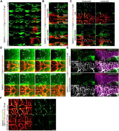
MC coverage of cranial vessels. (A) Confocal images of cranial region in the TgBAC(pdgfrb:EGFP);Tg(sox17:DsRed) embryo at 37 hpf. Dorsal view, anterior to the left. Multiple single z-plane images are shown (from the top (dorsal) to the bottom (ventral)). Left, pdgfrb:EGFP; right, the merged images of pdgfrb:EGFP(green) and sox17:DsRed(red). Note that EGFP-positive cells were not identical to DsRed-positive endodermal cells.(B) Confocal images of hindbrain vasculature in the 2 dpf TgBAC(pdgfrb:EGFP);Tg(fli1a:Myr-mCherry) embryos injected with control MO (upper two panels) or both kdrl and kdrMOs (lower two panels). Upper, pdgfrb:EGFP; lower, the merged images of pdgfrb:EGFP(green) and fli1a:Myr-mCherry(red). Arrowheads indicate the MCs covering the BA. Note that kdrl/kdr-double morphant exhibited not only defective formation of BA but also lack of MCs in the midline of the cerebral base. (C) Confocal images of CtA (upper tow panels) and the vessels in the cerebral base (BCA/PCS/BA, lower two panels) in the 3 dpf TgBAC(pdgfrb:EGFP);Tg(fli1a:Myr-mCherry) larvae injected with control MO (left column) or tnnt2aMO (right column). Upper, pdgfrb:EGFP; lower, the merged images of pdgfrb:EGFP(green) and fli1a:Myr-mCherry(red). Arrowheads indicate the MCs covering the BCA, PCS and BA.Note that MC coverage was observed in the vessels in the cerebral base but not in the CtA of tnn2a morphants. (D) Time-lapse confocal images of the cranial vasculature in the TgBAC(pdgfrb:EGFP);Tg(fli1a:Myr-mCherry) embryo (60-93 hpf). Dorsal view, anterior to the left. Upper, pdgfrb:EGFP; lower, the merged images of pdgfrb:EGFP(green) and fli1a:Myr-mCherry(red). Numbers indicate individual EGFP-positive cells emerging around the PCS and BCA. EGFP-positive cells designated with prime marks indicate progeny cells. (E) Confocal images of cranial vessels of pdgfrb heterozygous (upper two panels, sa16389/WT) and homozygous (lower two panels, sa16389/sa16389) larvae in theTgBAC(pdgfrb:EGFP);Tg(fli1a:Myr-mCherry) background at 5 dpf. Lateral view, anterior to the left. To assess blood flow and blood vessel lumenization, Qdot 655 fluorescent probe was injected into the common cardinal vein just before imaging.Upper left, pdgfrb:EGFP; lower left, Qdot 655; upper right, the merged images of pdgfrb:EGFP(green) and fli1a:Myr-mCherry(magenta); lower right, the merged images of pdgfrb:EGFP(green), fli1a:Myr-mCherry(magenta) and Qdot 655 (white). (F) Confocal images of CtA in the TgBAC(pdgfrb:EGFP);Tg(fli1a:Myr-mCherry) larva treated with vehicle (upper) or 20 µM AG1296 (lower) during 48-77 hpf. Dorsal view, anterior to the left. Left, the merged images of pdgfrb:EGFP(green) and fli1a:Myr-mCherry(red); right, pdgfrb:EGFP. BA, basilar artery; PHBC, primordial hindbrain channel; CCtA, cerebellar central artery; BCA, basal communicating artery; PCS, posterior communicating segment; CaDI, caudal division of the internal carotid artery; MtA, metencephalic artery. Scale bars, 50 µm. |
|
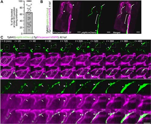
Extension of MC processes and MC migration along the inter-EC junctions. (A) Frequency of tip location of MC processes at the inter-EC junctions during their extension. By time-lapse imaging the TgBAC(pdgfrb:mCherry);Tg(fli1a:pecam1-EGFP) larvae as observed in Fig.3A, tip location of the MC process was examined every 15 or 20 min for more than 1 h. Data are expressed as a percentage of number of time points at which the tip of MC process located at the inter-EC junction among the total time points. Bar and circles indicate the average and the values of each process, respectively (n=36).(B) Confocal images of the MCs and inter-EC junctions in the CtA of the4dpf TgBAC(pdgfrb:mCherry);Tg(fli1a:pecam1-EGFP) larva. Left, fli1a:pecam1-EGFP; center, pdgfrb:mCherry; right, the merged image of fli1a:pecam1-EGFP(magenta) and pdgfrb:mCherry(green). Arrowheads indicate the inter-EC junctions visualized by Pecam1-EGFP, while arrows show the tip of MC processes. Brackets indicate the MC process aligned along the inter-EC junction. Asterisk indicates cell body of MC. The cell body of the MC shown in the left side of the image is out of frame. Scale bar, 10 µm.(C) Time-lapse confocal imagesof MC migration along the CtA in the hindbrain of the TgBAC(pdgfrb:mCherry);Tg(fli1a:pecam1-EGFP) larva. 3D-rendered confocal images and its subsequent time-lapse images with the elapsed time (min) at the top are shown, as in Fig. 3A. The boxed areas are enlarged beneath the original images. Dotted-lines in second and third rows of the leftmostcolumn outline the vessel morphology. Arrows indicate the tip of MC process, while asterisks show the cell body. Note that the tip of MC process moved forward along the inter-EC junction and that the MC-body (asterisks) was relocated to the preceding process which aligned along the inter-EC junctions (arrowheads). Scale bars, 10 µm. |
|
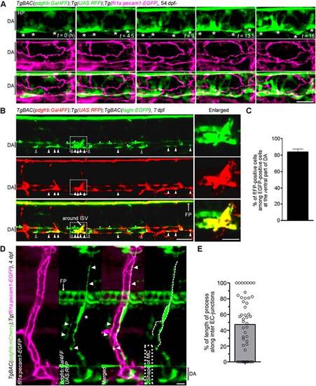
MC coverage of trunk axial vessels. (A) Time-lapse confocal images of MC coverage of DA. Confocal images of DA in the TgBAC(pdgfrb:Gal4FF);Tg(UAS:RFP);Tg(fli1a:pecam1-EGFP) embryo at 54 hpf(leftmost column) and subsequent time-lapse images with the elapsed time (h) at the bottom right. Top, pdgfr:Gal4FF;UAS:RFP(green); middle, fli1a:pecam1-EGFP (magenta); bottom, the merged images of pdgfr:Gal4FF;UAS:RFP(green) and fli1a:pecam1-EGFP(magenta). Asterisks indicate the cell body of MCs. Note that MCs located at the ventral side of DA extended multiple processes dorsally irrespective of inter EC-junctions. (B) Confocal images of trunk vasculature in the TgBAC(pdgfrb:Gal4FF);Tg(UAS:RFP);TgBAC(tagln:EGFP) larva at 7 dpf. Top, tagln:EGFP; meddle, pdgfr:Gal4FF;UAS:RFP; lower, the merged image of tagln:EGFP(green) and pdgfr:Gal4FF;UAS:RFP(red). The boxed areas are enlarged to the right. Open and closed triangles indicate the EGFP-positive and RFP-positive cells and the EGFP-positive and RFP-negative cells at the ventral side of the DA, respectively. Asterisks indicate the EGFP-positive and RFP-negative cells located in the dorsal and lateral side of the DA. (C) Percentage of RFP-positive cells among the EGFP-positive cells located at the ventral side of the DA, as observed in B. Data is mean ± s.e.m. (n = 15).(D) Confocal images of an ISV in the TgBAC(pdgfrb:mCherry);Tg(fli1a:pecam1-EGFP)larva at 4 dpf. Lateral view, anterior to the left. Leftmost panel, fli1a:pecam1-EGFP(magenta); second panel from the left, pdgfr:Gal4FF;UAS:RFP(green); third panel from the left, the merged image of fli1a:pecam1-EGFP image (magenta) and pdgfr:Gal4FF;UAS:RFP(green); rightmost panel, pdgfr:Gal4FF;UAS:RFP image in which MC shape is outlined by the dotted line. Arrowheads indicate the MC processes that aligned along with Pecam1-EGFP-labeled inter-EC junctions. Asterisk shows the MC body.(E) Alignment of MC processes along the inter-EC junctions as observed in Dis expressed as a percentage of the total length (n = 47). Bar and circles indicate the average and the values of individual process, respectively.In this figure, all images are shown in lateral view with anterior to the left.Scale bars; 20 µm (D,enlarged image in B)or 50 µm (A,B).DA, dorsal aorta; HP, hypochord; FP, floor plate. |
|
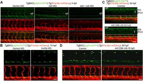
Developmental mechanism of MCsin the trunk vasculature. (A) Confocal images of trunk vasculature in the 3 dpf TgBAC(pdgfrb:EGFP);Tg(fli1a:Myr-mCherry) larvae injected with control MO (left), kdrlMO (center) or both kdrl and kdr MOs (right). Top, pdgfrb:EGFP; middle, fli1a:Myr-mCherry(red); bottom, the merged images of pdgfrb:EGFP(green) and fli1a:Myr-mCherry(red). (B) Confocal images of trunk vasculature in the 3 dpfTgBAC(pdgfrb:EGFP);Tg(fli1a:Myr-mCherry) embryo injected with control MO (left) or tnnt2aMO (right). Upper, pdgfrb:EGFP; lower, the merged images of pdgfrb:EGFP(green) and fli1a:Myr-mCherry(red). (C, D) Confocal images of trunk vasculature in the54 hpf (C) or 80 hpf (D)TgBAC(pdgfrb:EGFP);Tg(fli1a:Myr-mCherry)larvae treated with vehicle or 20 µM AG1296 during 32-53 hpf (C) or 48-79 hpf (D). Upper, pdgfrb:EGFP; lower, the merged images of pdgfrb:EGFP(green) and fli1a:Myr-mCherry(red). Arrows in C indicate the EGFP-positive cells beneath the DA. Yellow and blue arrowheadsin Dindicate the EGFP-positive cells covering aISVs and those covering vISVs, respectively. In this figure, all images are shown in lateral view with anterior to the left. Scale bars, 20 µm (enlarged image in A) or 50 µm (A-D).DA, dorsal aorta; PCV, posterior cardinal vein; HP, hypochord. |
|
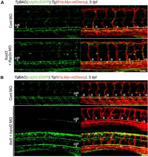
Investigation of the origin of the MCs in trunk vessels. (A) Confocal images of trunk vasculature in the 3 dpf TgBAC(pdgfrb:EGFP);Tg(fli1a:Myr-mCherry) larvae injected with control MO (upper) or both foxd3 and tfap2a MOs(lower). Left, pdgfrb:EGFP; right, the merged images of pdgfrb:EGFP(green) and fli1a:Myr-mCherry(red).(B) Confocal images of trunk vasculature in the 3 dpf TgBAC(pdgfrb:EGFP);Tg(fli1a:Myr-mCherry) larvae injected with control MO (top) or both tbx6 and hand2 MOs (middle and bottom). Left, pdgfrb:EGFP; right, the merged images of pdgfrb:EGFP(green) and fli1a:Myr-mCherry(red).In the bottom panel, GFP signal is intensified to detect the weak signal. HP, hypochord. “a” and “v” indicate arterial ISVs (aISV) and venous ISVs (vISV), respectively. Scale bars, 50 µm. |
|
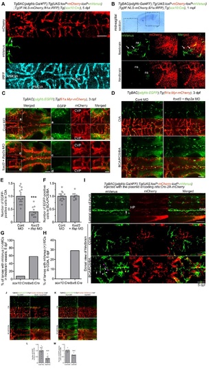
Investigation of the origin of the MCs in cranial vessels. (A) Confocal images of CtA in the TgBAC(pdgfrb:Gal4FF);Tg(UAS:loxP-mCherry-loxP-mVenus);Tg(IF:NLS-mCherry,fli1a:iRFP);Tg(sox10:Cre) larva at 5 dpf. The larvae expressing iRFP670 under the control of fli1a promoter was identified by intestinal fatty acid binding protein(IF) promoter-driven expression ofNLS-mCherry in the intestine. Dorsal view, anterior to the left. Top, mCherry; middle, mVenus; bottom, iRFP. Arrows indicate mVenus-positive MCs. Note that the mVenus-positive MCs existed in anterior part of MMCtA, but not in the PMCtA and CCtA, at 5 dpf. (B) Midsagittal section of brain of the TgBAC(pdgfrb:Gal4FF):Tg(UAS:loxP-mCherry-loxP-mVenus);Tg(IF:NLS-mCherry,fli1a:iRFP);Tg(sox10:Cre) juvenile at 1 mpf. Confocal images of forebrain (middlepanel) and hindbrain (bottom panel) indicated by the boxed areas in the bright field image (upper panel). Left, mVenus; center, mCherry; right, the merged images of mVenus (green) and mCherry (red). Arrows indicate mVenus-positive MCs. Note that the mVenus-positive MCs existed in the forebrain, but not in the hindbrain, at 1 mpf. ns indicates non-specific intrinsic fluorescence signal. (C) Confocal images of the vessels in the cerebral base in the 3 dpf TgBAC(pdgfrb:EGFP);Tg(fli1:Myr-mCherry) larvae injected with control MO (upper panels) or both foxd3 and tfap2a MOs (lower panels). Dorsal view, anterior to the left. The merged images of pdgfrb:EGFP(green) and fli1a:Myr-mCherry(red) are shown at the leftmost column. Boxed areas (a-d) are enlarged to the right, showing pdgfrb:EGFP(left), fli1a:Myr-mCherry(center) and the merged images of pdgfrb:EGFP(green) and fli1a:Myr-mCherry(red) (right). Note that pdgfrb:EGFP-positive cells around CVP were dramatically reduced in the foxd3/tfap2a-double morphant larvae. (D) Confocal images of CtA (upper two panel) and the vessels in the cerebral base (lower two panels, BCA/PCS/BA) in the 3 dpf TgBAC(pdgfrb:EGFP);Tg(fli1a:Myr-mCherry) larvae injected with control MO (left column) or both foxd3 and tfap2a MOs (right column). Dorsal view, anterior to the left. Upper, pdgfrb:EGFP; lower, the merged images of pdgfrb:EGFP(green) and fli1a:Myr-mCherry(red). (E, F) The number of EGFP-positive cells covering the CtA (E) or the BCA, PCS and BA (F), as observed in D. Data are expressed relative to the average of controls(n ≥ 9). (G,H) Percentage oflarvae showing mVenus-positive MCs covering the vessels in the hindbrain such as CCtA, BCA, PCS and BA (G) or in the CCtA (H) of the 5 dpf TgBAC(pdgfrb:Gal4FF):Tg(UAS:loxP-mCherry-loxP-mVenus)larvae crossed with Tg(sox10:Cre) (sox10:Cre)or Tg(tbx6:Cre,myl7:EGFP) (tbx6:Cre) fish line (sox10:Cre n=13, tbx6:Cre n=31). (I) Confocal images of trunk (upper panel; lateral view, anterior to the left) and head (middle (CCtA) and lower (BCA, PCS,and BA) panels; dorsal view, anterior to the left) regions in the 5 dpf TgBAC(pdgfrb:Gal4FF):Tg(UAS:loxP-mCherry-loxP-mVenus) larvae injected with the plasmid encoding ntla:Cre-2A-mCherry. Note that mVenus-positive MCs covered the ventral part of DA (arrow) in the trunk and the CCtA, BCA (white arrowheads), PCS (magenta arrowheads), BA (yellow arrowheads) and PMCtA (arrows) in the head. HP; hypochord. (J) Confocalimages of the CtA (upper two panels) and the vessels in the cerebral base (BCA/PCS/BA, lower two panels) in the 3 dpf TgBAC(pdgfrb:EGFP);Tg(fli1a:Myr-mCherry) larvae injected with control MO (left column) or both tbx6 and hand2 MOs (right column). Upper, pdgfrb:EGFP; lower, the merged images of pdgfrb:EGFP(green) and fli1a:Myr-mCherry(red). Note that tbx6/hand2-double morphant exhibited defective formation of hindbrain vessels. (K) Confocal images of the CtA and the vessels in the cerebral base in the 3 dpf TgBAC(pdgfrb:EGFP);Tg(fli1a:Myr-mCherry) larvae injected with control MO (left column) or tbx6 MO (right column) are shown, as in J. (L, M) The number of EGFP-positive cells covering the CtA (L) or the BCA, PCS and BA (M), as observed in K. Data are expressed relative to the average of controls(n ≥ 8). Bars and circles indicate averages and each value, respectively. Scale bars, 20 µm(enlarged images in C) or 50 µm(A-D, I-K). In E, F, Land M, bars and circles indicate averages and each value, respectively. In E, Land M, ***p<0.001, significant difference between two groups. |
|
Investigation of the origin of MCs in the hyaloid vessels and the vessels in the pharyngeal region. (A) Confocal images of hyaloid vessels in the 3 dpfTgBAC(pdgfrb:EGFP);Tg(fli1a:Myr-mCherry) larvae injected with control MO (upper panels in A and B)or either both foxd3 and tfap2a MOs (lower panel in A) or both tbx6 and hand2 MOs (lower panel in B). Lateral view, anterior to the left. Left, pdgfrb:EGFP; center, the merged images of pdgfrb:EGFP (green) and fli1a:Myr-mCherry(red); right, fli1a:Myr-mCherry. (C, D) Confocal images of vessels in the pharyngeal region in the 4 dpfTgBAC(pdgfrb:EGFP);Tg(fli1a:Myr-mCherry) larvae injected with control MO(left columns in C and D) or eitherboth foxd3 and tfap2a MOs (right column in C) or foxd3 MO (right column in D). Top, pdgfrb:EGFP; middle, the merged images of pdgfrb:EGFP (green) and fli1a:Myr-mCherry(red); bottom, fli1a:Myr-mCherry.In D, the boxed areas are enlarged to the right. Note that foxd3/tfap2a-double morphant larva exhibited severe structural defects in the head, although it could form abnormal HA. AA, aortic arches; HA, hypobranchial artery.Scale bars, 20 µm (enlarged image in D) or 50 µm (A-E). |


