|
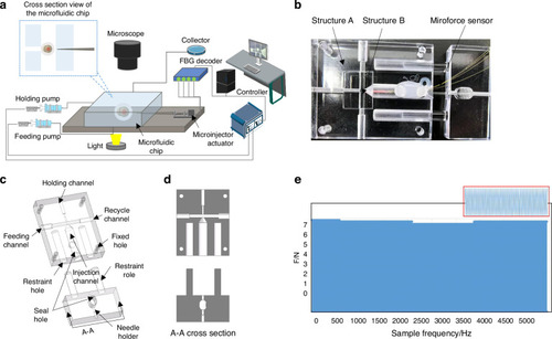
System setup. a Schematic diagram of microinjection system. The system is mainly composed of an injection module, a vision module, and a control module. The injection module consists of a microfluidic chip and a microsyringe with force sensing. The vision module and control module includes a computer, a microscopic camera, and a motion controller. b Microinjection chip. c Design details of microfluidic chip three-dimensional (3D) model. The microfluidic chip has four channels to connect to external devices. The right channel is connected to a microinjector for cell puncture and injection of foreign substances. The middle channel connects two micropumps for cell delivery and recovery. The left channel is connected to the suction pump for cell fixation. d A-A Cross-section of a microfluidic chip. e Fatigue test of sealant
|