
Fig. 1
- ID
- ZDB-FIG-240422-24
- Publication
- Pontius et al., 2024 - Magnetically powered microwheel thrombolysis of occlusive thrombi in zebrafish
- Other Figures
- All Figure Page
- Back to All Figure Page
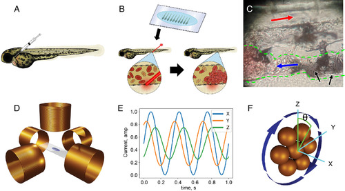
Generation of µwheels. (A) tPA and/or microparticles were infused via the retro-orbital space or PCV using pulled capillary micropipettes. (B) 3 dpf zebrafish larvae were mounted in low melting point agarose on glass coverslips and a pulsed dye laser was used to injure the endothelium of the PCV, resulting in thrombosis. (C) Photograph of µwheels at the site of a clot. Red and blue arrows indicate the direction of blood flow in the arterial and venous systems, respectively. Black arrows indicate the µwheels at the upstream edge of an occlusive thrombus, outlined with green dashes. (D) Zebrafish larvae mounted in low melting point agarose and infused with microparticles were placed in the center of five solenoid coils. (E) A laptop running MuControl software connected to a function generator and amplifier sends alternating currents to the x, y, and z coils. (F) The rotating magnetic field (blue arrows) induced by the coils causes the assembly and translation of the µwheels with steering controlled by the camber angle (θ) of the field relative to the z-axis. |