Fig. 1
- ID
- ZDB-FIG-240222-36
- Publication
- Cassidy et al., 2023 - Systematic analysis of proximal midgut- and anorectal-originating contractions in larval zebrafish using event feature detection and supervised machine learning algorithms
- Other Figures
- All Figure Page
- Back to All Figure Page
|
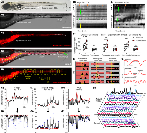
Manual and automated annotation of fluorescence contrasted contractions in larval zebrafish. (A) Wild-type AB zebrafish larvae at 7–8 dpf. The gut is outlined (dotted white line) and the region used to acquire image time series is outlined (solid white line, 10× objective). Anterior/posterior (A/P) and dorsal/ventral (D/V) axis shown. Bright field (B) and fluorescence (C) images of the gut of a 7 dpf larva following immersion in E3 with Nile Red. The dashed and dotted white line in B–C shows the spatiotemporal track drawn in the CellSens program to generate the bright field (D) and fluorescence (E) STMs for the same larva. Arrows in D–E annotate proximal midgut-originating retrograde (yellow; pRC) and anterograde (green; pAC) contractions propagating through the gut over time. Orange arrows in E annotate anorectal-originating retrograde contractions (aRC), orange arrows in D correspond to the same location. A/P axis shown for the position along the gut. (F) Paired comparisons of the number of pRC and pAC counted in the STMs for bright field and fluorescence image time series by three independent experimenters. Sample size = 7 larvae, 1 bright field, and 1 fluorescence STM per larva. Results from each experimenter were analyzed independently (refer to Table 1 for ANOVA results). **p < 0.01, ***p < 0.001. (G) Merged image with the different functional segments of the gut outlined and labeled. Directionality of pRC (yellow arrow), pAC (green arrow), and aRC (orange arrow) labeled. (H) Positioning of the analysis (#1–19) and reference (#20) ROIs used to extract fluorescence intensity time series. (I) Spatiotemporal propagation of pRC in the foregut (left), pAC in the midgut/hindgut (middle), and aRC (right) in relation to the ROIs, and (J) the resulting pattern of fluorescence intensity fluctuations in each ROI. Example FIBSI workflow for detection of pRC in the foregut (K, N), pAC in the midgut/hindgut (L, O), and aRC (M, P). Depending on the directionality of the fluorescence fluctuations, FIBSI constructed a peak-to-peak or trough-to-trough reference (red line; K, L, M) from a sliding median (not shown). That reference was then normalized to y = 0 and the resulting residuals were used for event detection (N, O, P). Event peaks (blue X) were identified only for the waveforms with start/end times where y = 0 (red X). (Q) Example gut motility patterns taken from fluorescence intensity series in ROIs 1–19 and represented on a normalized scale. |

