
Image
|
Figure Caption
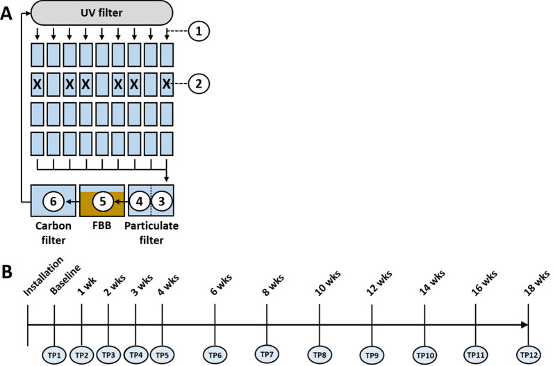
Fig. 1
Schematic diagram of the recirculating system, and the sampled sites including post-UV disinfection water (1), tank water from six different tanks in which fish were introduced following collection of baseline samples, denoted by X (2), pre-particulate filter water (3), post-particulate filter water (4), the fluidized bed biofilter (FBB) (5), and carbon filter water (6) (
Acknowledgments
This image is the copyrighted work of the attributed author or publisher, and
ZFIN has permission only to display this image to its users.
Additional permissions should be obtained from the applicable author or publisher of the image.
Full text @ Anim Microbiome