
|
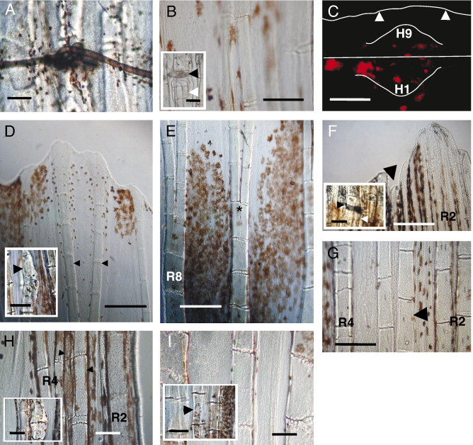
Fig. 4 Regenerated recombinant rays with hemirays from different origins can be obtained after hemiray fragment grafting and cut at the level of the graft. (A) The hemiray graft was fixed by a knobbed loop of a very thin surgical thread. (B) After cut, homotopical graft of an H3 fragment of the caudal fin leads to a symmetrical normal R3. Inset shows the homotopical graft proximal to the level of the cut. The black arrowhead shows the thread used for the graft. The white arrowhead shows the grafted fragment. (C) Transversal section of a recombinant H1 → H9 ray in which H1 was labeled with DiI. DiI-labeled cells were observed in one side of the ray blastema (H1). However, some positive cells were also observed in the contralateral side (H9) within the blastemal mesenchyme. Epidermal cells were never stained in the contralateral side (arrowheads). (D) Distal and proximal (inset) detail of an H1 → H9 recombinant regenerate. The ray bifurcates (arrowheads) and shows a pattern and size similar to the neighboring rays. The inset includes the grafted fragment (arrowhead) remaining at the stump. White cells (small, rounded and orange in color) are pigment cells characteristic of R1 rays (Johnson et al., 1995) and are observed in the grafted region. (E) Intermediate region of the H1 → H9 regenerate showing bifurcating (asterisk) contralateral hemirays with a symmetrical pattern. (F) Distal and proximal (inset) detail of an H9 → H3 regenerate. Observe that the regenerate (arrowhead) shows a size similar to the neighboring rays. The inset includes the stump of the regenerate showing the grafted fragment. The black arrowhead shows the thread used for the graft. The white arrowhead shows the grafted fragment. (G) Detail of an intermediate position of an H9 → H3 regenerate (arrowhead) showing hemirays with a symmetrical pattern. R4 and R2 means rays 4 and 2 in any lobe. (H) Distal and proximal (inset) details of an H3p → H3d graft regenerate. Observe the recombinant ray bifurcates (arrowheads) at the level of the neighboring R4 ray. The inset includes the remaining graft fragment at the level of the cut. (I) A detail of a medial region of an H3d-H3p recombinant ray regenerate. Observe the symmetrical pattern that shows the recombinant regenerate. The black arrowhead shows the grafted fragment. Scale bar represents 300 μm (D, E), 125 μm (F, G and in inset of panels D, F, H, and I), 100 μm (B, C, H, I and in inset of panel B) and 50 μm (A).
Reprinted from Developmental Biology, 312(1), Murciano, C., Pérez-Claros, J., Smith, A., Avaron, F., Fernández, T.D., Durán, I., Ruiz-Sánchez, J., García, F., Becerra, J., Akimenko, M.A., and Marí-Beffa, M., Position dependence of hemiray morphogenesis during tail fin regeneration in Danio rerio, 272-283, Copyright (2007) with permission from Elsevier. Full text @ Dev. Biol.