
- Title
-
Modular multimodal platform for classical and high throughput light sheet microscopy
- Authors
- Bernardello, M., Gualda, E.J., Loza-Alvarez, P.
- Source
- Full text @ Sci. Rep.
( |
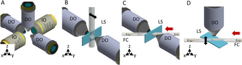
(A) The objectives’ configuration enabling multiple illumination/detection schemes. (B) Through the first mounting option the sample is embedded within a cylinder perpendicular to the optical table. The black arrow indicates the scanning direction. (C) The second approach uses the flow of the samples to scan them through the light sheet. The red arrow indicates the flow direction. (D) Through the third approach, the sample flow (red arrow) is used to position the sample in the objective’s FoV of the DO. The scanning of the specimen is obtained instead in the vertical direction (black arrow), either mechanically or optically. IO illumination objective, DO detection objective, LS light sheet, FC fluidic circuit. Figure created with Autodesk Inventor Professional 2015 (www.autodesk.com). |
( |
( |
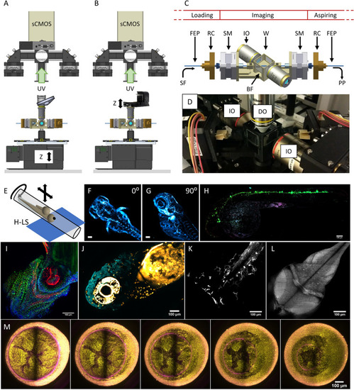
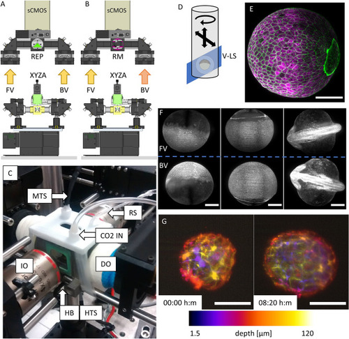
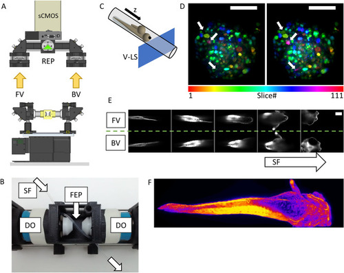
Setup implementation in the Hybrid LSFM modality with upright detection scheme and examples. The scanning in the depth (z) direction can be performed either (A) through a vertical stage moving the entire chamber or (B) through the displacement of the detection objective with a piezo-element synchronized with galvanometric scanning of the light sheet. Schematic (C) and actual implementation (D) of the imaging chamber for the Hybrid LSFM modality. (E) Exemplification of the sample mounting and scanning system. The sample flows within the FEP tube until the objectives’ FoV. There, it can be rotated around the FEP tube’s axis to orient the sample correctly (as shown in F, G) and/or it can be moved in a controlled and stepwise manner along the tube, providing multichannel high-resolution whole larvae imaging by stitching (H). (I) The system allowed high-throughput imaging of zebrafish heart in a single imaging session (18 samples. The showed image was processed through a background correction method to decrease yolk’s auto-fluorescence). Full set of images in Supplementary Fig. 7. The use of a piezo focus control (B) allows fast imaging of macrophage migration in the head (J) and the caudal fin (K) as well as zebrafish brain’s neural activity using calcium indicators (L). More information in Supplementary Videos 5, 6 and 7. (M) Long-term multicolor time-lapse movies of zebrafish embryo development are also achieved. Scale bars: 100 µm. UV upper view, SF sample flow, RC rotational connector, SM stepper motor, W water compartment, PP programmable pump (not shown), BF bright field compartment, IO illumination objective, DO detection objective. (A, B) created with FreeCAD 0.16 (www.freecadweb.org) and (C, E) created with Autodesk Inventor Professional 2015 (www.autodesk.com). |