FIGURE SUMMARY
Title

Pyramidal Neurons of the Zebrafish Tectum Receive Highly Convergent Input From Torus Longitudinalis

Authors
DeMarco, E., Tesmer, A.L., Hech, B., Kawakami, K., Robles, E.
Source
Full text @ Front. Neuroanat.

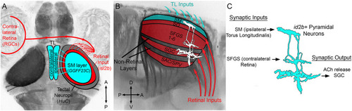
Overview of TL-tectum circuit and PyrN connectivity. (A) Dorsal view fluorescence image of a Tg(HuC:lynTagRFP-t) larval brain in which all axon tracts and neuropil areas are fluorescently labeled, with superimposed schematic of the brain regions examined in this study. Connectivity of TL-tectum circuitry: ipsilateral TL forms an axonal projection terminating in the SM layer of the tectal neuropil. The contralateral retina forms an axonal projection terminating in tectal layers distinct from SM. (B) Higher magnification side view of the midbrain of brain volume in (A). Overlayed schematic depicts the relative laminar positions of retinal input layers relative to SM, other non-retinorecipient neuropil layers, and PyrN stratification pattern. (C) Putative connectivity of id2b:gal4 positive PyrNs. Based on laminar position of dendrites PyrNs most likely receive TL-derived inputs on their SM dendrite and retinal inputs on their SFGS dendrite. PyrN axon stratifies within the SGC layer.

hspGGFF23C transgenic labels TL neurons that project to SM. (A,B) Low-resolution confocal images of 7 dpf triple transgenic Tg(hspGGFF23C,uas:egfp,isl2b:tagRFP) larva from side- and dorsal-view. (C) Higher magnification maximum projection images of TL and one tectal lobe of larva in (A,B). Merged fluorescence channel shown in (C), hspGGFF23C-driven EGFP channel shown in (C). Note presence of EGFP-positive cells in TL and neurite plexus formed in tectal neuropil and lack of labeling in SPV layer of tectum. (D) Single confocal image through tectal neuropil. Note discrete EGFP labeling in the superficial SM layer of tectal neuropil. (E) Rotated side-view of image volume in (D), orientation orthogonal to the neuropil layers. (F) Fluorescence intensity profile measurement along line indicated by box in (E). Note peak in EGFP signal in the superficial SM layer. Scale bar: 300 μm in (A,B), 80 μm in (C), and 60 μm in (D,E).

Axonal projection from TL to tectum is glutamatergic. (A) Dorsal view confocal image of EGFP and DsRed fluorescence in the brain of a Tg(hspGGFF23C,uas:egfp,vglut2b:rfp) larva. (B) Magnified views of region indicated by box in (A) showing the EGFP (B), DsRed (B′), and merged (B′′) fluorescence channels. Arrows indicate neurons with EGFP and DsRed colocalization. (C) Van Steensel's cross-correlation functions of EGFP and DsRed overlays. Local maxima of Pearson's Coefficient (PC) near ΔX = 0 indicates colocalization. N = 10 larvae. (D) Dorsal view confocal image of the tectum in a 7 dpf Tg(hspGGFF23C,uas:egfp) larva fixed and immunofluorescently stained with anti-EGFP antibody. Note dense plexus of EGFP-positive axons in SM. (E) Side-view of a single tectal lobe from tectum in (D), including immunofluorescent staining with anti-VGluT1 antibody in red channel. Note superficial EGFP labeling in SM layer and punctate VGluT1 immunofluorescence. Note increased density of puncta in SM layer. (F) High-resolution dorsal view of a SM subregion within tectum in (D). Note overlap between VGluT1 puncta and EGFP-positive plexus and lack of VGluT1 labeling in EGFP-negative regions. (G) Van Steensel's cross-correlation functions of EGFP and DsRed overlays for image in (F′). Local maxima of Pearson's Coefficient (PC) near ΔX = 0 indicates colocalization. N = 4 larvae. Scale bar: 150 μm in (A), 30 μm in (B,E), 75 μm in (D), and 15 μm in (F).

PSD95-positive post-synaptic specializations in PyrN dendrites. (A) Maximum projection of PSD95-EGFP and DsRed expression in an isolated id2b:gal4 positive PyrN. Note discrete enrichments of PSD95-EGFP relative to cytosolic DsRed label. (A′) +50° Y-axis rotated view of image volume in (A). SM, SFGS, and SGC dendritic portions are indicated by boxed regions. Note presence of PSD95-EGFP puncta in SM, SFGS, and SGC layer dendrites. (B) −40° Y-axis rotated views of isolated subvolumes from boxed regions in (A′) showing PSD95-EGFP and DsRed expression in the SM, SFGS, and SGC dendrites. (C) Threshold images of PSD95-EGFP channel in rotated subvolumes in (B) as an example of threshold values used for automated particle analysis (puncta counting). (D–F) Quantification of PSD95-EGFP puncta number, neurite length, and puncta density for SM, SFGS, and SGC dendrite subregions in 7 fully reconstructed PyrNs obtained from 7 larvae. Scale bar: 20 μm in (A) and 15 μm in (B,C). *p < 0.05; **p < 0.001; ANOVA with Tukey's post-hoc test.

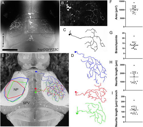
Morphology of individual TL axons innervating SM. (A) Dorsal view confocal image of the midbrain from a 7 dpf Tg(hspGGFF23C:gal4,uas:NTR-mCherry) larva containing several labeled neurons in the left TL lobe and a single neuron in the right TL lobe, indicated by boxed region. (B) Magnified view of boxed region in (A). (C) Skeletonized tracing of SMTL neuron in (B). Note large, sparsely branched arbor. (D) Skeletonized tracings of three SMTL neurons. Note large, sparsely branched arbor and small dendritic arbors within TL. (E) Dorsal view inverted fluorescence image of the brain of a Tg(HuC:lynTagRFP-t) larva. Overlayed on the right tectum are reconstructed and appropriately scaled tracings of three SMTL neurons in (D) that innervated SM. Note that the three SMTL neurons vary in their cell body position within TL, but all are located in ipsilateral TL. Overlayed on the left tectum are convex polygons that summarize the SM area spanned by each of the three SMTL axons shown at right. (F–I) Quantification of retinotopic area, branchpoint number, total neurite length, and branching density for 16 reconstructed SMTL axons obtained from 12 larvae. Scale bar: 120 μm in (A), 80 μm in (B–D), and 90 μm in (E).

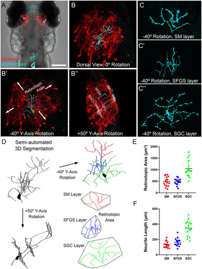
Morphometry of PyrN arbors formed in SM, SFGS, and SGC layers of tectum. (A) Dorsal view, whole-brain confocal image volume of a 7 dpf double transgenic Tg(id2b:gal4,uas:NTR-mCherry) larva injected at the embryo stage with a uas:egfp-caax plasmid to yield sparse genetic labeling. Note single EGFP-labeled neuron in each tectal lobe. (B) Higher magnification maximum projection of neuron labeled in right tectal lobe of larva in (A). Projection is shown from dorsal view, 0° Y-Axis rotation. Maximum projection of same neuron rotated −40° about the Y-axis, an orientation parallel to the tectal layers (B). Maximum projection of same neuron rotated +50° about the Y-axis, an orientation orthogonal to the tectal layers (B′′). Note clearly stratified neurite morphology with arbors in SM, SFGS, and SGC layers of tectal neuropil. (C) High magnification views of isolated subvolumes of the SM (C), SFGS (C), and SGC (C′′) layer dendrites of neuron in B shown with −40° Y-axis rotation used to calculate retinotopic areas. (D) Workflow for morphological segmentation and measurement of retinotopic areas for PyrN neurite subvolumes. Semi-automated 3D segmentation produces skeletonized tracings used for neurite length and retinotopic area measurements. For direct comparison between raw images and tracings, note that skeletonized tracing was obtained from PyrN shown in (B,C). (E,F) Quantification of retinotopic area and neurite length measurements for the different PyrN neurite subvolumes: SM, SFGS, and SGC. Scale bar: 200 μm in (A), 50 μm in (B), 15 μm in (C), and 20 μm in (D).

Evidence for high degree of convergence from TL inputs to PyrNs. (A) Maximum projection image of fluorescence in a 7 dpf Tg(HuC:lynTagRFP-t) larva. (B) Maximum projection of boxed subregion in (A) rotated −40° about the Y-axis, an orientation orthogonal to the tectal layers used for retinotopic area measurements. Maximum projection of equivalent subregions in a 7 dpf Tg(hspGGFF23C,uas:egfp,isl2b:TagRFP) larva rotated −40° about the Y-axis. Yellow polygon drawn to assist in comparison of area differences between the three images. (C) Schematic at left summarizes tectal inputs from TL-recipient SM layer (cyan), retinorecipient layers (red), and total tectal neuropil area. Schematic at right summarizes area measurements for these different neuropil layers. (D) Skeletonized tracings and average retinotopic areas for TL axons, RGC axons, and PyrN neurite subregions. (E) Implications of size disparity between TL axon arbors and retinal axon arbors in tectum. TL axon arbor areas are depicted as cyan circles and RGC axon arbor areas are red ovals. Due to the large size of TL arbors, a PyrN dendrite at the center of SM has the potential to contact all TL inputs. Conversely, the small relative size of RGC axons innervating SFGS means that a PyrN dendrite at the center of SFGS has the potential to contact only a small fraction of retinal inputs to SFGS. Due to the small size of both pre- and post-synaptic elements this remains true even as the number of RGC inputs increases. Scale bar: 200 μm in (A) and 100 μm in (B).

Acknowledgments
This image is the copyrighted work of the attributed author or publisher, and ZFIN has permission only to display this image to its users. Additional permissions should be obtained from the applicable author or publisher of the image. Full text @ Front. Neuroanat.