
|
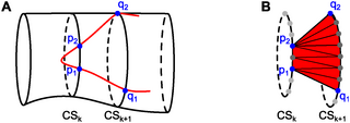
Fig. 5 Triangulation within a projected cell contour. (A) In red, part of the projected cell contour on the smoothed vessel cross-sections is shown. To triangulate the part of the cell surface between cross-sections k and (k + 1), the edges (p1, q1) and (p2, q2) of the projected cell contour between these two cross-sections are identified. (B) A triangulation connects the cross-sectional path between p1 and p2 and the cross-sectional path between q1 and q2 within the cell surface. This triangulation is performed for each pair of neighboring vessel cross-sections that contains parts of the cell surface.