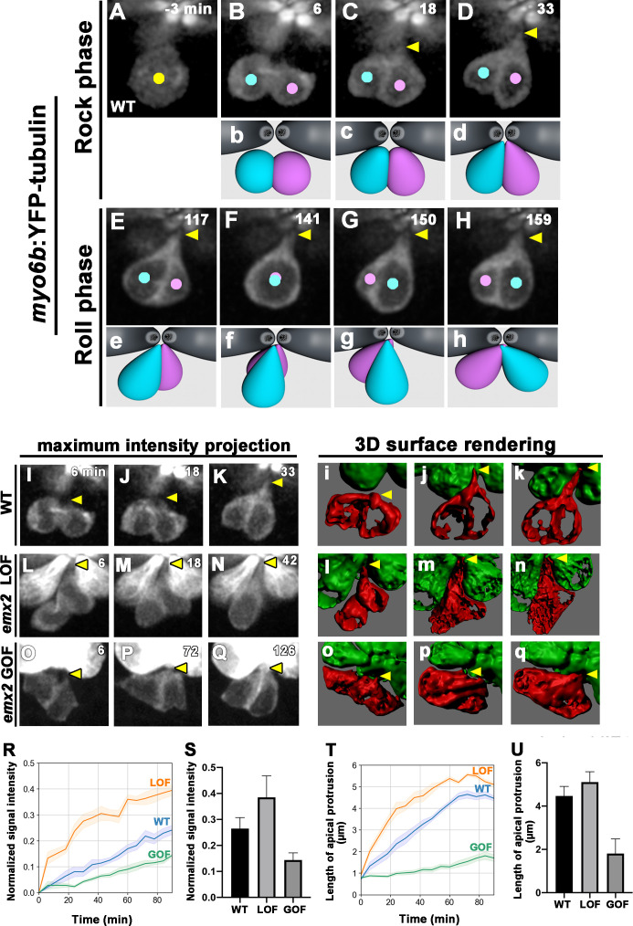
Figure 6 (A–H) Time-lapse images of myo6b:YFP-tubulin (wild-type [WT]) transgenic line showing nascent HCs undergoing Rock and Roll. After precursor cell divides (A), sibling HCs form an apical protrusion within 30 min of the Rock phase (B–D, yellow arrowhead, n = 6). When they exchange positions at the Roll phase, they appear to be pivoted at the apex (E–H, yellow arrowheads). Animation of images is shown in respective panels (Rock phase: b–d, Roll phase: e–h). (I–Q) Maximum intensity projection images generated by selected slices along z-axis in WT (I–K, same sample of A–H, n = 3), emx2 loss of function [LOF] (L–N, n = 3) and emx2 gain of function (GOF) (O–Q, n = 3). (i–q) Three-dimensional surface rendering of selected time points of live-imaging of HC pairs (red) in WT (i–k, n = 3), emx2 LOF (l–n, n = 3), and emx2 GOF (o–q, n = 3) neuromasts. Mature HCs are labeled in green. (R) Increases of YFP-tubulin signal intensity at the apical region of nascent HCs of WT (n = 5), emx2 LOF (n = 5), and emx2 GOF (n = 6) during the Rock phase (90 min). The shaded area represents the standard error of the mean (SEM). (S) YFP-tubulin signal intensities of the apical protrusion at the end of Rock phase were significantly different among WT (n = 5), emx2 LOF (n = 5), and emx2 GOF HCs (n = 6, one-way ANOVA, F = 26.97, p<0.0001); post-hoc Dunnett’s multiple comparisons test for WT vs. LOF, p=0.0073, WT vs. GOF, p=0.0052. (T) Increases over time in the length of apical protrusion in WT (n = 5), emx2 LOF (n = 5), and emx2 GOF (n = 5) during the Rock phase (90 min). The shaded area represents the SEM. (U) The length of apical protrusion at the end of the Rock phase in WT (n = 5), emx2 LOF (n = 5), and emx2 GOF (n = 5) were compared. Significance was assessed by using one-way ANOVA, F = 52.15, p<0.0001. Post-hoc Dunnett’s multiple comparisons test for WT vs. LOF is not significant (p=0.148) but significant for WT vs. GOF (p<0.0001). The following figure supplement, source data, videos are available for Figure 6—figure supplement 1. Measurements of signal intensity and length of the apical protrusion using Image J Fiji.
Image
Figure Caption
Acknowledgments
This image is the copyrighted work of the attributed author or publisher, and
ZFIN has permission only to display this image to its users.
Additional permissions should be obtained from the applicable author or publisher of the image.
Full text @ Elife

