FIGURE SUMMARY
Title

The effects of temperature on the proxies of visual detection of Danio rerio larvae: observations from the optic tectum

Authors
Babkiewicz, E., Bazała, M., Urban, P., Maszczyk, P., Markowska, M., Gliwicz, Z.M.
Source
Full text @ Biol. Open

The experimental results. (A) Detection distance (mean+1s.d.), (B) duration of peaks (mean+1s.d.), (C) full width at half maxima of peaks (FWHM, mean+1s.d.), and (D) the time between two adjacent peaks (mean+1s.d.) assessed for the peaks of relative florescence reflecting neural activity in a region of the OT in response to the visual stimuli at three temperature treatments. Results that share the same letter do not differ significantly from each other.

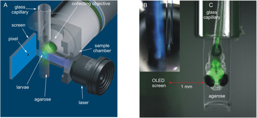
Position of zebrafish larvae and miniature OLED screen inside the sample chamber of a Lightsheet Z.1 microscope and photographs showing the glass capillary with zebrafish larvae and OLED screen inside the sample chamber of the microscope. (A) Perspective view (modified picture from the ZEISS Lightsheet Z.1 Light Sheet Fluorescence Microscopy for Multiview Imaging of Large Specimens). (B) The position of the glass capillary with zebrafish larva relative to the screen surface. Photo taken with a camera located on the inside part of the door leading to the sample chamber of the microscope. (C) An enlargement showing larvae illuminated with a laser light.

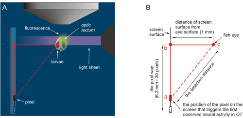
Pictures showing the zebrafish larva inside the glass capillary and the OLED screen inside the sample chamber of the microscope and the scheme for estimating the detection distance. (A) Top view. Note that the red triangle represents the relative position of the fish eye in relation to the screen and the position of the pixel on the screen, which induces the first neural signal in the OT (modified picture from the ZEISS Lightsheet Z.1 Light Sheet Fluorescence Microscopy for Multiview Imaging of Large Specimens). (B) A detailed scheme for designating the detection distance using the Pythagorean theorem. The red dotted line represents the length assumed to be the detection threshold distance.

Details of data analysis. (A) Experimental time-lapsed images (without enlargement in the upper panel and with enlargement in the lower panel) analysed in ZEN software, with the red ring marking the ROI. Note that at starting, the time-point intensity of fluorescence was at the basal level and increased as the visual stimulus approached and moved opposite to the fish eye. (B) An example of the florescence graph at 23°C with details of the measured parameters on the peaks and the scheme of the correspondence of the position of the visual stimulus on the OLED screen and the peak line.

Acknowledgments
This image is the copyrighted work of the attributed author or publisher, and ZFIN has permission only to display this image to its users. Additional permissions should be obtained from the applicable author or publisher of the image. Full text @ Biol. Open