IMAGE

Fig. 4.

ID
ZDB-IMAGE-250804-34
Source
Figures for Stark et al., 2025
Image
Figure Caption

Fig. 4.

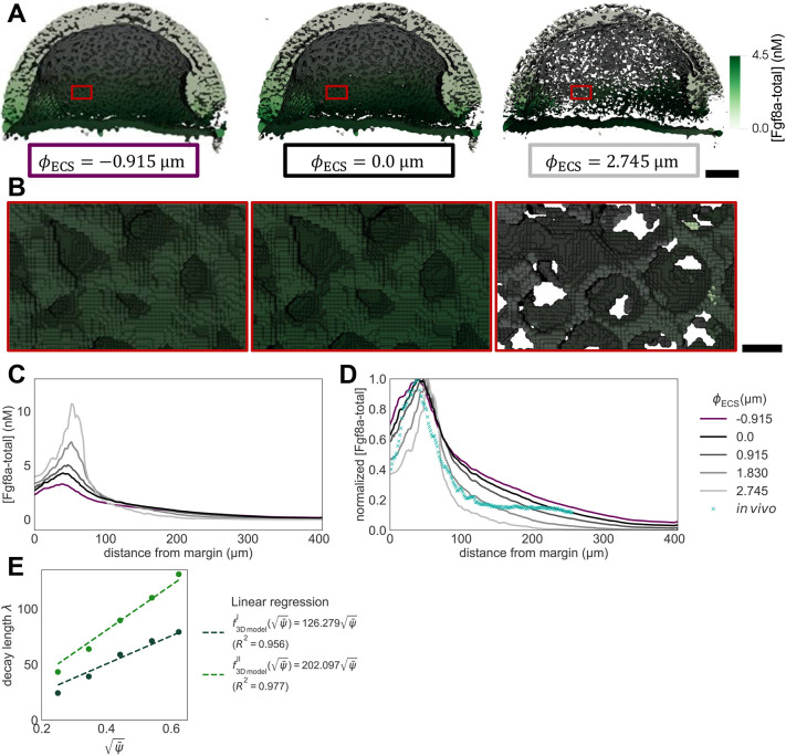
ECS geometry controls Fgf8a gradient steepness and range. To test how ECS tortuosity influences Fgf8a gradients, we simulated de novo gradient formation for different ECS geometries. (A) Clipped visualizations of the baseline ECS geometry (center) and two perturbed versions (left and right) with simulated Fgf8a concentrations overlaid in green, scaled to (see color intensity bar). The ECS tube thickness is perturbed by changing the boundary location along φECS: shifting down by one grid spacing h=0.915 μm (2 pixels), i.e. φECS=− 0.915 μm, to obtain thicker tubes; and increasing by 3h, i.e., φECS=2.745 μm to obtain thinner tubes. (B) Higher magnification images of the areas outlined in A. (C) Absolute AV concentration profiles at . Colors correspond to different geometries (see key). Compared to the baseline geometry (solid black line), decreasing ECS tube sizes limits Fgf8a propagation lengths and leads to a steeper gradient with a higher peak (gray lines), whereas increasing the ECS tube size leads to a flatter gradient (violet line). (D) The same profiles normalized to their respective maximum concentration values. The in vivo profile at 60% epiboly (symbol) is more similar to the simulated profile for thinner tubes of φECS=1.830 μm, the average decay length of which, , is close to the in vivo decay length λ. (E) Linear scaling of λI and λII with respect to . The linear fit is the least-squares solution obtained using numpy.linalg.lstsq (Harris et al., 2020). The key provides the fitted proportionality coefficients and their goodness of fit R2. Scale bars: 100 μm (A); 10 μm (B).

Acknowledgments
This image is the copyrighted work of the attributed author or publisher, and ZFIN has permission only to display this image to its users. Additional permissions should be obtained from the applicable author or publisher of the image. Full text @ Development