
|
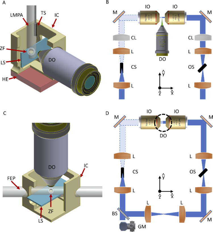
Fig. 1
Schematic of the LSFM mounting and scanning methods used. (A) The zebrafish embryo (ZF), within its chorion, is embedded inside a lmpa cylinder hanging from the top of the imaging chamber (IC) and connected to a translation-rotational stage, to enable the scan through the vertical light-sheet (LS). The emitted photons are collected by the detection objective (DO). A heating element (HE) is integrated below the chamber, while a temperature sensor (TS) is immersed in the imaging medium to monitor the temperature for the whole experiment. (B) Schematic of the illumination optical path for the first LSFM setup. Each of the two illumination arms contains two lenses (L) and a cylindrical lens (CL) for the LS formation. After reflection on a mirror (M), the illumination objective (IO) generates the vertical LS in the sample plane. The illumination paths also contain two shutters (CS = closed shutter, OS = open shutter), that are employed to block the light from one of the two arms, generating the alternate illumination scheme. (C) A FEP tube crosses at 45° the imaging chamber, creating a fluidic circuit through which the embryo is loaded and then positioned in the FoV of the detection objective. Once here, the entire chamber (and the attached FEP tube) is displaced vertically to scan the sample across the horizontal LS. The imaging chamber models are here sectioned to ease visualization of the interior part. (D) Schematic of the illumination optical path for the second LSFM setup. A galvanometric mirror (GM) generates the LS that through a beam-splitter (BS) is sent to each illumination objective, to create the horizontal LS at the sample plane. The dotted circumference denotes the position of the vertical detection objective. Shutters are again used to implement the double alternate excitation scheme.