
|
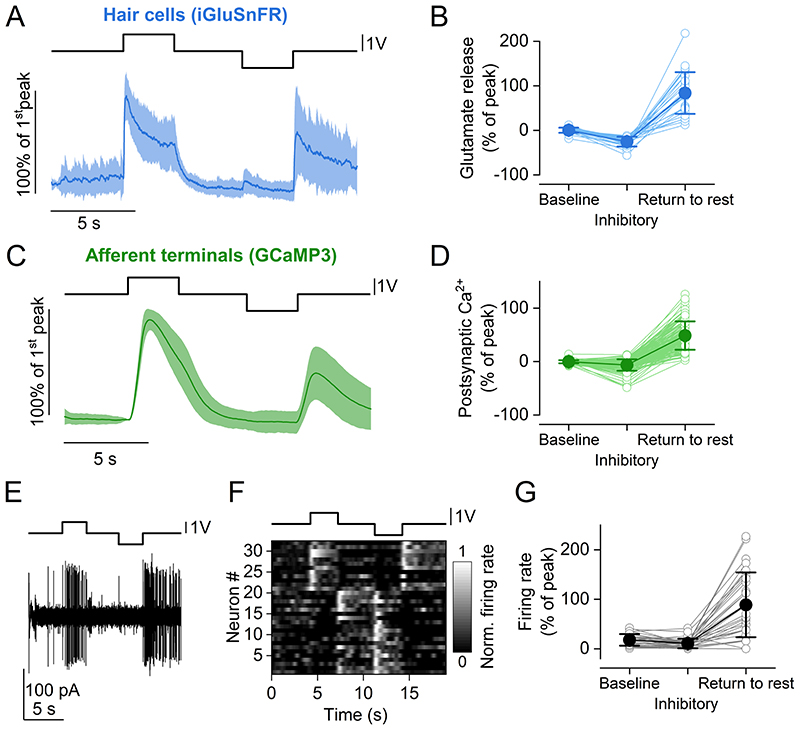
Figure 8 A, average time course of iGluSnFR responses to two consecutive saturating stimuli (duration: 3s) in opposite directions (excitatory and inhibitory) from 26 hair cells (23 neuromasts, 15 zebrafish). Top trace: fluid jet driving voltage. B, glutamate release at three different time points of the stimulus. Values are normalised to the maximum response calculated during the first 2 s of the stimulus (Peak). Baseline: average ΔF/F0 before stimulation. Inhibitory: minimum ΔF/F0 during the inhibitory step. Return to rest: maximum ΔF/F0 in the 3 s after the termination of the inhibitory stimulation. The return to rest response was visible in the majority of hair cells tested (26 out of 28 hair cells). C, average trace of postsynaptic Ca2+ responses to two 3 s saturating stimuli in opposite directions (excitatory and inhibitory) detected as change in GCaMP3 fluorescence emission from 143 afferent terminals (69 neuromasts, 35 zebrafish). D, postsynaptic Ca2+ responses during the delivery of the stimulus. Values are normalised to the maximum response calculated during the first 2 s of the stimulus (Peak). Baseline, Inhibitory and Return to rest were calculated as in (B). E, representative electrophysiological recording from one afferent neuron while stimulating a connected neuromast. Note the increase in firing rate both for the positive (excitatory) pressure stimulus and at the return to rest from the negative (inhibitory) stimulus. F, raster plot of individual afferent neuron activity during the application of two 3 s saturating stimuli in opposite directions. The firing rate is normalised to the peak of the firing activity during the excitatory step and was calculated by convolving the spike train with a Gaussian kernel (σ = 200 ms). G, quantification of PLLg neuron activity during the delivery of the stimulus (32 neurons, 16 zebrafish). Values are normalised to the maximum response calculated during the first 2 s of the stimulus (Peak). Baseline, Inhibitory and Return to rest were calculated as in (B). In (A) and (C), continuous traces represent the mean and the shaded areas represent the SD. In (B), (D) and (G), filled symbols denote average values and open symbols represent individual recordings.