
Figure 3
- ID
- ZDB-IMAGE-200612-17
- Publication
- Hartmann et al., 2020 - An image-based data-driven analysis of cellular architecture in a developing tissue
- All Figures
- Figures for Hartmann et al., 2020
|
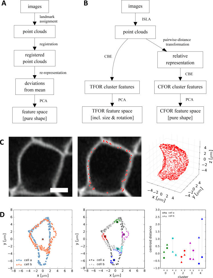
Figure 3 (A) A classical workflow in landmark-based geometric morphometrics. (B) Adapted workflow for morphometrics of arbitrary fluorescence intensity distributions. See Figure 3—figure supplement 1 for a more detailed version. (C) Illustration of ISLA, our algorithm for conversion of voxel-based 3D images to representative point clouds. Shown are a slice of an input image (left), here a membrane-labeled cell in the pLLP (scale bar: 2 μm), the landmarks sampled from this image (middle), here oversampled compared to the standard pipeline for illustration purposes, and the resulting 3D point cloud (right). (D) Illustration of CBE, our algorithm for embedding point clouds into a feature space. In this 2D mock example, two cells are being embedded based on point clouds of their outlines (left). CBE proceeds by performing clustering on both clouds combined (middle) and then extracting the distances along each axis from each cluster center to the centroid of its ten nearest neighbors (right). Note that the most distinguishing morphological feature of the two example cells, namely the outcropping of cell a at the bottom, is reflected in a large difference in the corresponding cluster's distance values (cluster 4, blue).