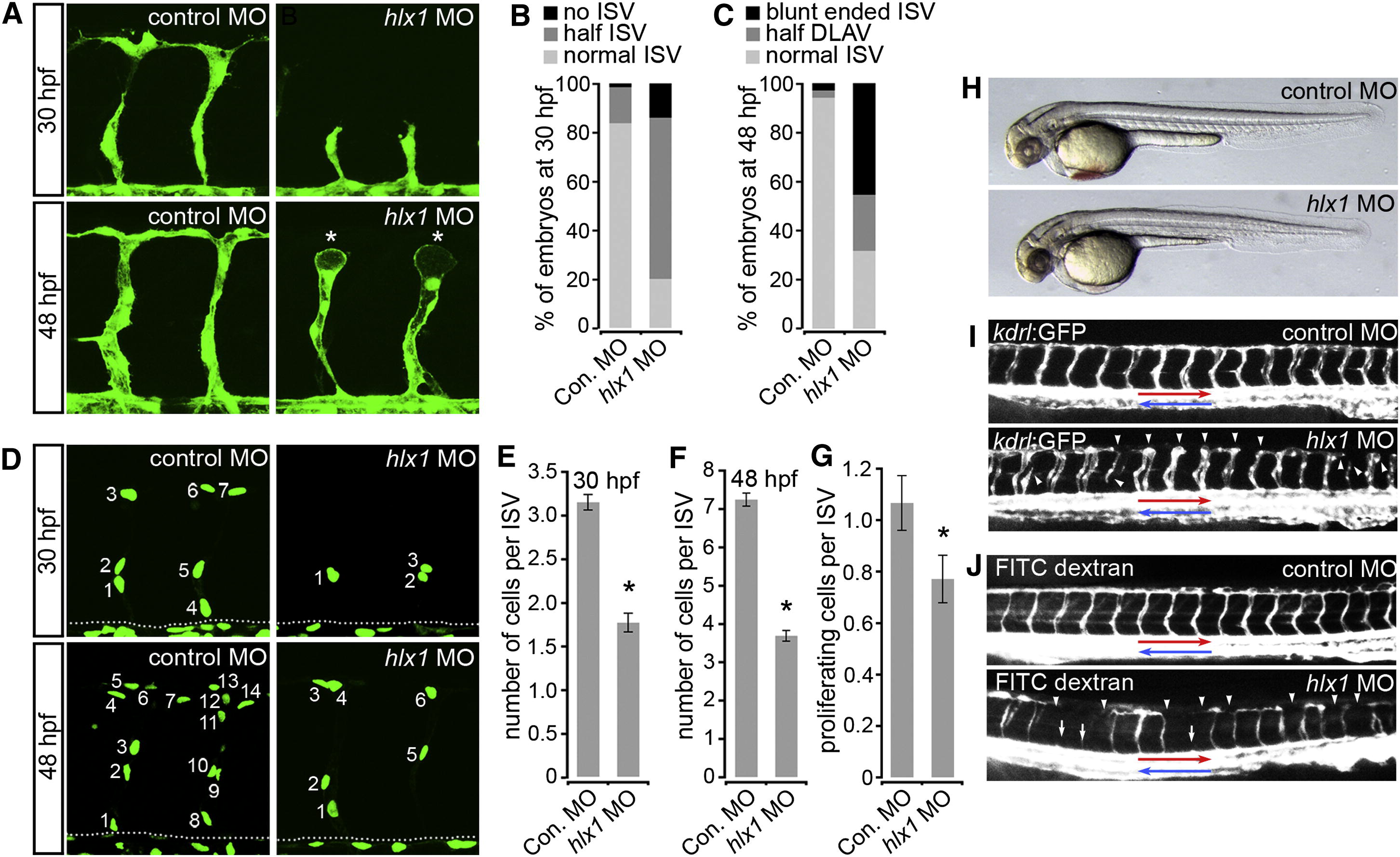
Fig. 3 Hlx1 Is Required for ISV Angiogenesis In Vivo(A–F) Lateral views of Tg(kdrl:GFP)s843 (A) or Tg(kdrl:nlsEGFP)zf109 (D; dotted line represents position of the DA) embryos and quantification of ISV morphology (B and C; “half DLAV” refers to ISVs connected to only one adjacent ISV; n = at least 20 embryos) or ISV EC numbers (E and F; n = at least 15 embryos) at 30 (B and E) and 48 (C and F) hpf upon injection with either control MO (Con. MO) or hlx1 MO.(G) Quantification of the number of dividing ECs per ISV following live imaging of control or hlx1 MO-injected embryos from 19 hpf for approximately 13 hr (n = at least 30 ISVs from a total of 8 embryos).(H and I) Lateral views of control or hlx1 MO-injected Tg(kdrl:GFP)s843 embryos at 48 hpf (red arrows indicate DA; blue arrows denote cardinal vein). Hlx1 knockdown disrupts ISV sprouting (as indicated by asterisks in A and arrowheads in I), limits EC incorporation into ISVs (D–F), and reduces EC proliferation (G).(J) Lateral views of control or hlx1 morphants upon injection of FITC-dextran into the blood flow to assess vascular patterning at 48 hpf. White arrows indicate ISVs lacking blood perfusion. Red and blue arrows indicate arterial and venous blood flow, respectively. Arrowheads indicate ISVs that lack connections with adjacent ISVs. Blood flow through ISVs is disrupted upon Hlx1 knockdown.Error bars represent mean ± SEM. p < 0.05 versus control, Student′s t test. See also Figures S2 and S3 and Movies S1 and S2.
Image
Figure Caption
Figure Data
Acknowledgments
This image is the copyrighted work of the attributed author or publisher, and
ZFIN has permission only to display this image to its users.
Additional permissions should be obtained from the applicable author or publisher of the image.
Full text @ Curr. Biol.

