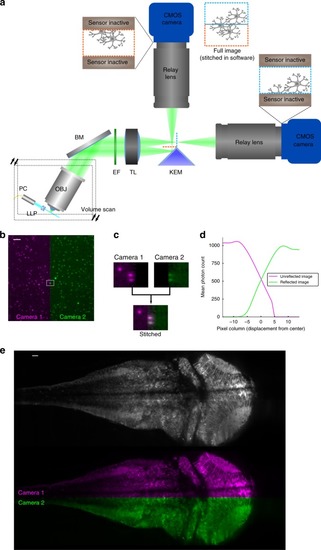
Mitigating the camera bottleneck. a A two-camera shared-image OCPI system. A knife-edged prism mirror (KEM) takes the place of the camera sensor in Fig. 1b. The mirror is aligned so that half of the image is reflected and relayed to a camera above while half passes unimpeded and is relayed to a second camera. Cameras are aligned so that they image a centered horizontal band in the field of view. The two cameras expose synchronously, and their images are later stitched together into a full image. Since the frame rate of a CMOS camera depends only on image height (Fig. 1e) this doubles the imaging speed of the system. b Example stitched image of fluorescent beads (0.2 μm diameter) with one camera’s image in magenta and the other in green. Scale bar: 20 μm. c Zoomed view of the rectangular region marked in panel b showing a pair of beads in the narrow region imaged by both cameras, corresponding to the apex of the KEM. d Quantification of a stitched image of fluorescene dye solution with the same width and location as shown in panel c. The width of the redundant image region is approximately 10 pixels (less than 0.3% of the camera chip width). e Pseudocolored and grayscale views of the same stitched slice of a larval (5 dpf, HuC:GCaMP6s) zebrafish brain. Scale bar: 20 μm
|

