
Fig. 4
- ID
- ZDB-FIG-110128-24
- Publication
- Koyama et al., 2011 - Mapping a sensory-motor network onto a structural and functional ground plan in the hindbrain
- Other Figures
- All Figure Page
- Back to All Figure Page
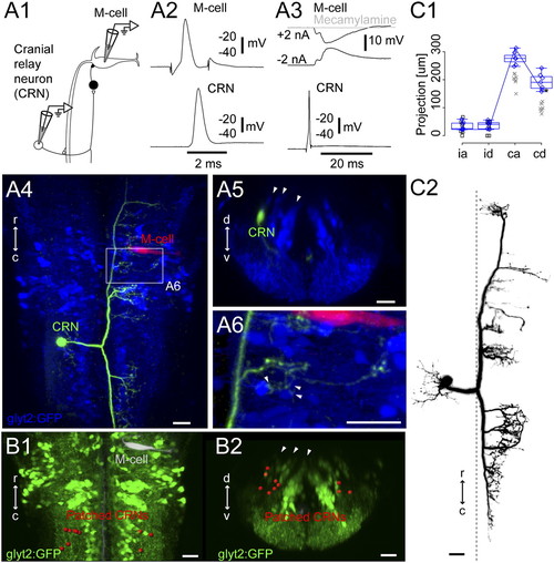
Cranial relay neurons. (A1) Pairwise recordings of a GFP-negative cranial relay neuron at rhombomere 7/8 and the contralateral M-cell in the Tg(glyt2:GFP) x relaxed line at 4 dpf. (A2) Firing the M-cell led to an action potential in the cranial relay neuron. (A3) Firing the cranial relay neuron with current injection led to a long-latency IPSP in the M-cell (black) that was blocked by application of the cholinergic blocker mecamylamine (100 μM, gray). (A4) Top-down view of the recorded cranial relay neuron (green) and the M-cell (red) relative to glycinergic neurons (blue). (A5) Cross-section of the cranial relay neuron at rhombomere 8. Arrowheads mark glycinergic stripes. (A6) Close up of axonal terminations from the cranial relay neuron in region of the white rectangle in A4 showing apposition (arrowheads) to glycinergic neurons in the region. (B1 and B2) Locations of 10 cranial relay neurons at rhombomeres 7/8 (red) identified with pairwise recordings, in top-down (B1) and cross-section (B2) views. (C1 and C2) Summary of the morphology of seven cranial relay neurons, laid out as in Fig. 2C. Xs mark neurons whose whole axonal extent was not captured after recording. Box-and-whisker plots are from seven electroporated cells marked with blue diamonds whose whole axonal extent was captured. Asterisk marks a point on the line shown for the neuron in C2. (Scale bars, 20 μm.) |