
- Title
-
Comprehensive Hydrodynamic Investigation of Zebrafish Tail Beats in a Microfluidic Device with a Shape Memory Alloy
- Authors
- Subendran, S., Kang, C.W., Chen, C.Y.
- Source
- Full text @ Micromachines (Basel)
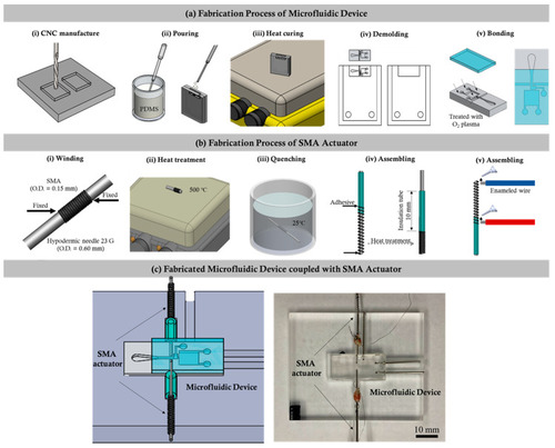
The fabrication process of the microfluidic and shape memory alloy (SMA) device. (a) i–v illustrates the various fabrication processes involved in the making of the proposed microfluidic device. (b) i–v illustrates the series of fabrication processes involved in the fabrication of the SMA device. (c) Illustration of the fabricated microfluidic device with the SMA integrated together. |

Illustration of the microfluidic device actuating operation using the SMA. (a) (i) and (b) (i) are the pictorial illustrations of the microfluidic device before and after the actuation process. (a) (ii) and (b) (ii) are the microphotographs captured before and after the actuation process. |

(a) The microphotograph of the zebrafish (6 d.p.f.) fixed in the observation region for tail quantification time. (b–d) The hydrodynamic quantificational measures of the zebrafish tail beating. The vorticity field (color map) is overlapped with the velocity vector field (black arrows) generated during tail beatings of zebrafish larvae (6 d.p.f.). (e) Instantaneous circulation formation due to the hydrodynamic right and left tail beating of zebrafish larvae (4, 5, and 6 d.p.f.) with effective test samples in each experimental group (N = 10). |

Effects of the cochineal red additive on tail-beating force of zebrafish larvae (4, 5, and 6 d.p.f.). Zebrafish larvae (5 and 6 d.p.f.) showed a transit change in the tail-beating force hydrodynamically with effective test samples in each experimental group. Significant differences between the control and the exposure groups are indicated by asterisks, (* p < 0.05) and (** p < 0.01) as compared with the control for 4, 5 d.p.f. (N = 10), and 6 d.p.f. (N = 30). |