IMAGE

Fig. 2

ID
ZDB-IMAGE-240219-32
Source
Figures for Spratt et al., 2023
Image
Figure Caption

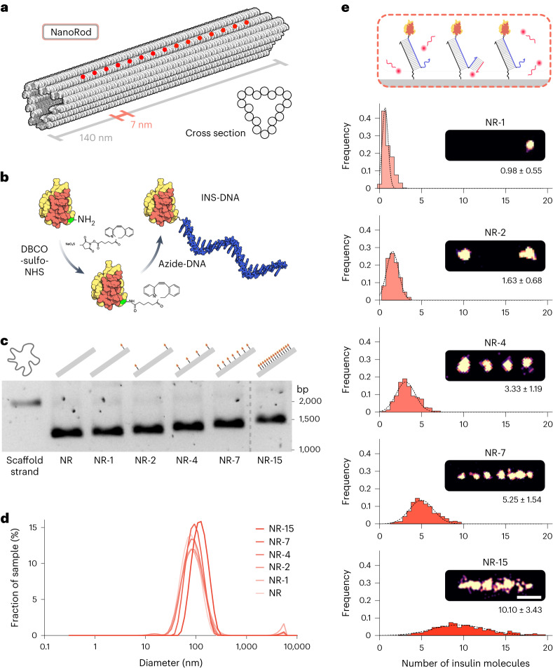
Fig. 2 Insulin NanoRods with programmable insulin configurations.

a, Representation of the DNA origami NanoRod. The red circles correspond to the positions of protruding DNA strands at programmable positions along one of its faces used for hybridization to INS-DNA. b, Overview of the method used to conjugate a single azide-modified ssDNA oligonucleotide to the B29 lysine of insulin (green) using a DBCO-sulfo-NHS crosslinker (not drawn to scale). c, Agarose gel electrophoresis of the scaffold strand and of insulin NanoRods with 0 (NR), 1 (NR-1), 2 (NR-2), 4 (NR-4), 7 (NR-7) and 15 (NR-15) insulin molecules. The image is representative of three independent experiments. d, Analysis of the indicated insulin NanoRods by dynamic light scattering. e, Schematic of DNA-PAINT used to image INS-DNA bound to the NanoRods. Distribution of the occupancy of insulin on the indicated insulin NanoRods. The values presented under the images correspond to mean ± s.d. Scale bar, 50 nm.

Source data

Acknowledgments
This image is the copyrighted work of the attributed author or publisher, and ZFIN has permission only to display this image to its users. Additional permissions should be obtained from the applicable author or publisher of the image. Full text @ Nat Nanotechnol