
|
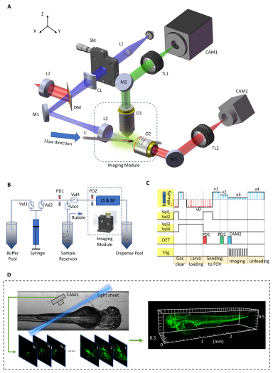
Fig. 1 Principle of the high-throughput 3D imaging system, LS-FIS. (A) Sketch of the LS-FIS optics. L1-L3: lens; CL: cylinder lens; DM: dichroic mirror; M1-M3: mirror; O1-O2: objective; TL1-TL2: tube lens; CAM1-CAM2: camera; C: capillary. See Visualization 1. (B) Sketch of the LS-FIS fluidics. The fluidic flow was driven by a syringe pump between the buffer pool, sample reservoir, and dispense pool and controlled by two three-way valves and two photon-detectors. Val1-Val4: electromagnetic valve; LS: light sheet imaging; BF: bright filed imaging. See Visualization 2. (C) Timeline to reverse the pump, change the flow rate, open/close the valves with the signals from photon-detector PD1 (red) & PD2 (green), and the signal to trigger the imaging camera (blue). DET: detection of larva arrival; Trig: camera trigger. (D) Reconstruction of 3D embryo image by stacking light-sheet images with the correction of larva translational position.