IMAGE

Fig 4

ID
ZDB-IMAGE-210224-27
Source
Figures for Bohns et al., 2020
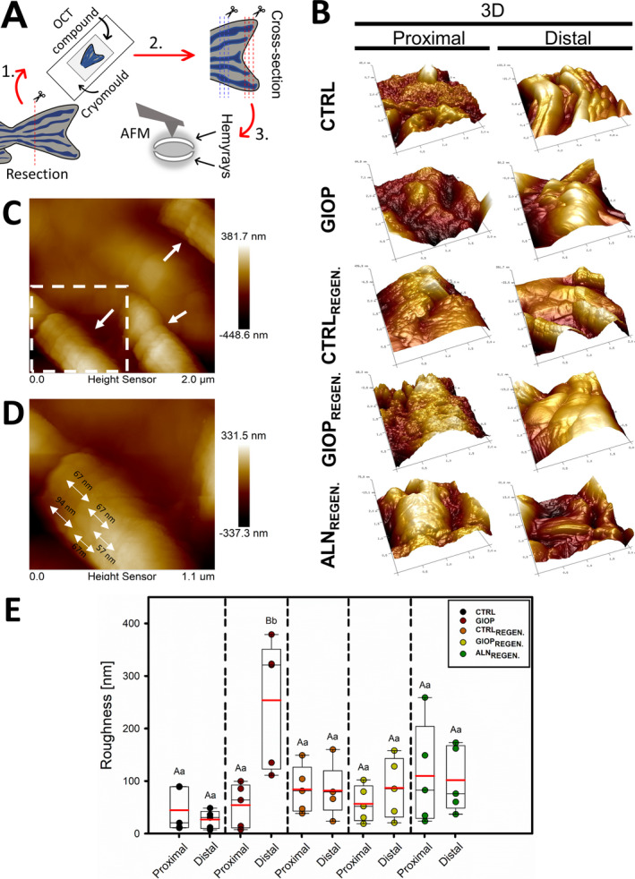
Image
Figure Caption

Fig 4

Surface topography profile of zebrafish bony rays and roughness calculation. (A) Procedure steps from the resection of the zebrafish caudal fins, to the analysis with AFM in tapping‐mode. (B) 3D representation of the cross‐section slices (obtained by cryosection process) analyzed by AFM. (C) The distal part of CTRLREGEN group showing collagen fibers bundles (white single arrows) in flattened representations. (D) Approximation of the collagen fiber bundle from the white square in “B”; the double arrows shows the diameter of a periodic unit from a fibril (d ~ 75 nm). (E) Box‐plots with means (red horizontal line) and median (black horizontal line) of the roughness obtained from proximal and distal parts of fins by AFM. Capital letters indicate significant statistically difference between the different regions (proximal and distal) within the same treatment (p < .01). Lowercase letters indicate significant statistically difference between the same region (proximal or distal) among different treatments (p < .01).

Acknowledgments
This image is the copyrighted work of the attributed author or publisher, and ZFIN has permission only to display this image to its users. Additional permissions should be obtained from the applicable author or publisher of the image. Full text @ JBMR Plus