IMAGE

Fig. 4

ID
ZDB-IMAGE-200910-9
Source
Figures for Kumar et al., 2020
Image
Figure Caption

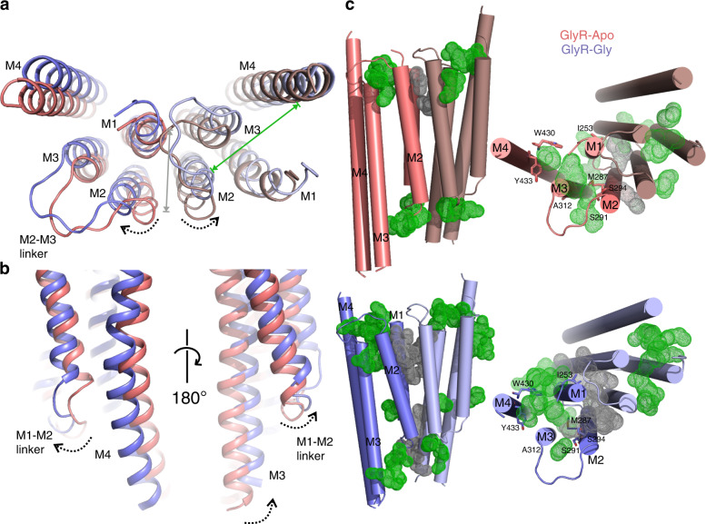
Fig. 4 Conformational changes in the M4 helix and the effects on internal cavities.

a An overlay of GlyR–Apo and GlyR–Gly. The TMD viewed from the top reveals repositioning of TM helices. The intra-subunit and inter-subunit cavities are indicated by green and gray arrows, respectively. b Extent of conformational change in the ICD formed by the pre-M4 region, the M1–M2 linker, and the post-M3 region. The direction of movement is highlighted by black arrows. c A comparison of the inter-subunit (gray dots) and intra-subunit (green dots) cavities in GlyR–Apo (top) and GlyR–Gly (bottom) predicted using F pocket algorithm61. The cavities predicted on the surface were removed for clarity. The right and left panels are side and top views, respectively. The residues shown in sticks on the left panel are implicated in binding allosteric ligands45.

Acknowledgments
This image is the copyrighted work of the attributed author or publisher, and ZFIN has permission only to display this image to its users. Additional permissions should be obtained from the applicable author or publisher of the image. Full text @ Nat. Commun.