
Image
|
Figure Caption
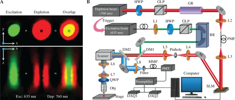
Figure 1:
Principle and experiment system of STED microscopy.
(A) Focal spots of the excitation beam and the depletion beam, and their overlap in both XY plane and XZ plane. (B) Schematic of the STED imaging system. L, lens; HWP, half wave plate; GLP, Glan-laser polarizer; GR, glass rod; RR, retro reflector; M, mirror; DM, dichroic mirrors; Obj, objective lens; QWP, quarter wave plate; SMF, single mode fiber; PMF, polarization maintaining fiber; MMF, multimode fiber; DAQ, data acquisition device.
Acknowledgments
This image is the copyrighted work of the attributed author or publisher, and
ZFIN has permission only to display this image to its users.
Additional permissions should be obtained from the applicable author or publisher of the image.
Full text @ Nanophotonics