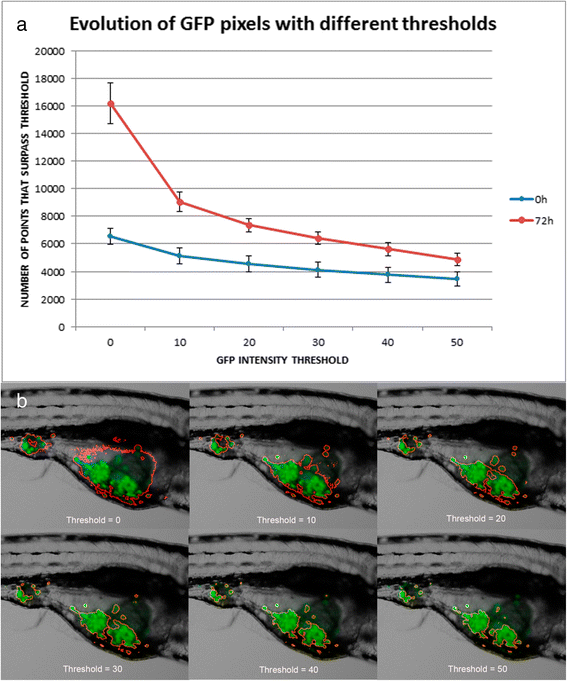
Fig. 2
Evolution of the number of GFP pixels based on GFP intensity thresholds for zebrafish embryos and regions of interest of fluorescent zebrafish applied with different thresholds. a Graphical representation of average GFP intensity thresholds on the x-axis and mean number of pixels greater than the threshold on the y-axis for the zebrafish embryos tested (n = 6). A progressive decay of the area, more evident at 72 hpi (dotted lines), is shown. It can also be observed that as the threshold increases, the area decreases slightly. At a low threshold, auto-fluorescence can represent an important component of GFP intensity. However, as soon as this threshold is raised, auto-fluorescence drastically disappears. Blue line represents 0 hpi embryos, and red line represent 72 hpi embryos. b Example of segmentation in evolution with red outlines over the images with thresholds from 0 to 50. The region inside the red outline is reduced as the threshold increases. This way the brightest pixels with higher fluorescence are selected, eliminating the majority of auto-fluorescence from the zebrafish embryo

