- Title
-
Cell-accurate optical mapping across the entire developing heart
- Authors
- Weber, M., Scherf, N., Meyer, A.M., Panáková, D., Kohl, P., Huisken, J.
- Source
- Full text @ Elife
|
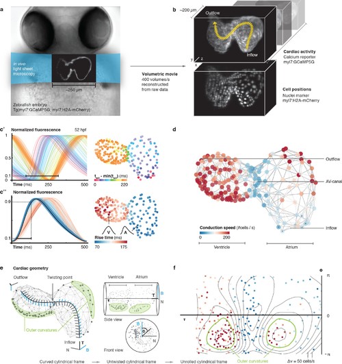
In vivo 3D optical mapping reveals cell-specific calcium transient patterns at 52 hr post fertilization (hpf). (a) Transmitted light microscopy image with ~250 µm-sized, two-chambered heart (shown as fluorescence image with light sheet illumination path). (b) Genetically encoded fluorescent markers expressed in myocardial cells report calcium transient activity and cell positions. Volumetric movies were reconstructed from multiple high-speed movies, each with a temporal resolution of 2.5 ms and a voxel size of 0.5 µm in xy and 1 µm in z. Image data are available at Weber et al. (2017). (c’) Normalized fluorescence plot of every cell’s calcium transient over one cardiac cycle. The network’s activation timing (tact) is visualized in 3D based on the time-point of 10% calcium transient amplitude in every individual cell (right, same color scale). (c’’) Normalized fluorescence plot of all calcium transients, aligned in time based on the timing of deviation from minimal fluorescence intensity (3D network, same color scale). (d) Biological conduction speed, expressed as cells activated per unit of time, is visualized on the 3D network. (e) The basis vectors of the local coordinate system (tangent – black, normal – grey, and binormal – blue) are shown, moving along the centerline. The initial and final orientation of the moving reference frame is shown in a zoomed version at inflow and outflow sites. Outer curvature regions of atrium and ventricle are highlighted in green. (f) The unrolled cylinder results in a representation of 3D network function in a 2D map. Projections show conduction speed across the entire myocardium; iso-velocity lines (Δv = 50 cells/s) are shown in black. Outer curvature regions in atrium and ventricle are highlighted in green. |
|
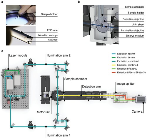
High-speed light sheet microscopy for in vivo 3D optical mapping. (A) A zebrafish embryo is mounted in agarose inside a fluorinated ethylene propylene (FEP) tube. (B) Section view of the sample holder with mounted zebrafish embryo placed inside the medium-filled sample chamber. The embryo is placed in the field of view of the detection objective and illuminated with a static light sheet from one of two sides. (C) Top view of the high-speed light sheet microscope for in vivo cardiac imaging. The laser module combines a 488 and a 561 nm laser line and sends the beam into the two illumination arms. Both arms generate identical light sheets from two opposite sides. The motor unit positions the sample holder with the mounted zebrafish embryo at the intersection of illumination and detection path. Fluorescence emission is split and recorded with an sCMOS camera running at up to 400 Hz. |
|
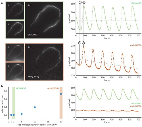
Comparison of the calcium reporter GCaMP5G and the voltage reporter Arch(D95N) for multi-scale readout of cardiomyocyte activation. (a) Optical section across the atrium of a zebrafish embryo at 52 hpf expressing GCaMP5G and Arch(D95N) in cardiomyocytes. Both channels are recorded simultaneously. Smaller images: raw data recorded at the lowest (I) and highest (II) fluorescence signal, as indicated in the intensity plots. Note how intensity plots illustrate the known slight delay between intensity maxima of calcium versus voltage traces, and the overall excellent capture by both reporters of presence and temporal dynamics of cell activation. Larger images: results of image I subtracted from image II, presenting the maximum intensity difference (image brightness adjusted independently for better visibility). Plots show mean raw intensities over time measured along the myocardium visible in the images. (b) Laser powers in the field of view (measured at the back pupil of the illumination objective) used for the experiment presented in (a) and their impact on the heart rate (n = 3 zebrafish embryos). Arch(D95N) required 10x more laser power than GCaMP5G, yielded a very low signal with about 20 gray levels dynamic range across one cardiac cycle, and was affected by bleaching. Zebrafish embryos showed increased heart rate when illuminated with the high laser power needed for Arch(D95N) imaging. GCaMP5G showed a dynamic range of about 300 gray levels at an order of magnitude lower laser power, with no signs of visible photobleaching or illumination-induced increase in heart rate. |
|
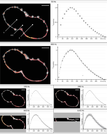
Evaluation of signal coverage and tracing precision using the fluorescent calcium reporter GCaMP5G at different recording speeds. Optical sections across the silenced heart of a 2 days post fertilization (dpf) zebrafish embryo expressing GCaMP5G and H2A-mCherry in cardiomyocytes, recorded at 50 to 3200 Hz (exposure times 20 to 0.3 ms) with a constant pixel size of (0.5 µm)2. Raw image data of H2A-mCherry are shown to mark cell positions. Red markers indicate location of peak fluorescence intensities across a single cardiac cycle. Gray areas in 800 Hz and 3200 Hz images indicate the proportion of the field of view that could not be recorded, as the number of lines imaged is the speed-limiting factor on the sCMOS camera. Plots show normalized fluorescence intensity over time, measured in a sub region with GCaMP5G signal. Circles show data points from the measurement at 50 Hz as reference. Higher recording speed results in a better representation of the calcium transient until 400–800 Hz, especially during the initial rise in intensity. At an even higher rate of 3200 Hz, noise deteriorates the signal. Peak intensities could be traced with cellular precision at 400 and 800 Hz, before signal noise reduced precision. |
|
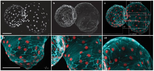
Myocardial morphology is heterogeneous across the heart at 52 hpf. Maximum intensity projections of point-scanning confocal and two-photon microscopy z-stacks recorded from a transgenic zebrafish embryo expressing myl7:H2A-mCherry and myl7:lck-EGFP in the myocardium. Scale bars: 50 µm. (a) Positions of myocardial nuclei (myl7:H2A-mCherry) across the heart. (b) Myocardial cell membranes (myl7:lck-EGFP). (c) Color overlay of cell membranes (cyan) and nuclei (red). (c1-3) Detailed view (rotated by −15 degrees about x–axis) of the cell morphologies in inflow, inner curvature and outer curvature regions of the atrium, as indicated in panel (c). |

