
- Title
-
Visualizing the metazoan proliferation-quiescence decision in vivo
- Authors
- Adikes, R.C., Kohrman, A.Q., Martinez, M.A.Q., Palmisano, N.J., Smith, J.J., Medwig-Kinney, T.N., Min, M., Sallee, M.D., Ahmed, O.B., Kim, N., Liu, S., Morabito, R.D., Weeks, N., Zhao, Q., Zhang, W., Feldman, J.L., Barkoulas, M., Pani, A.M., Spencer, S.L., Martin, B.L., Matus, D.Q.
- Source
- Full text @ Elife

(A) Schematic of the CDK sensor fused to GFP (top) or 2xmKate2 (bottom) and a nuclear mask (H2B::FP) separated by a self-cleaving peptide (P2A). Inset: nuclear localization signal (NLS), nuclear export signal (NES), and consensus CDK phosphorylation sites on serine (S) residues. (B) Schematic of CDK sensor translocation during the cell cycle. (C) Representative fluorescence overlay (bottom), H2B (top), and DHB::2xmKate2 (middle) time series images during embryo cell divisions (see Figure 1—video 1). Orange arrowheads follow the division of a single blastomere. (D) Confocal micrograph montage of CDK sensor expression in a C. elegans L3 stage larva. (D’) Three somatic tissues are highlighted (inset, dashed orange box) shown at higher magnification with pseudo-colored nuclei (magenta) depicting cells of interest. (E) Schematic of quantification and equation used to obtain the cytoplasmic:nuclear ratio of DHB. (F) Representative images of sensor expression in vulval precursor cells (VPCs) at peak G2 and 20 min after anaphase during G1 in DHB::GFP (gray) and DHB::2xmKate2 (magenta). Orange arrowheads indicate the VPCs. (G) Dot plot depicting G2 and G1 DHB ratios of the two CDK sensor variants in the VPCs (n ≥ 15 cells per phase). (H) Plot of DHB ratios in VPCs during one round of cell division, measured every 5 min (n ≥ 11 mother cells per strain). Dotted line indicates time of anaphase. Error bars and shaded error bands depict mean ± SD. (I) Representative images of sensor and PCNA expression in VPCs during G1 and S phase. Orange arrowheads indicate the VPCs. Blue arrowheads indicate S phase PCNA puncta. (J) Dot plot depicting G1 and S phase DHB::2xmKate2 ratios based on absence or presence of PCNA puncta (n ≥ 10 cells per phase). **p≤0.01, ****p≤0.0001. Significance determined by statistical simulation; p-values in Supplementary file 1. Scale bar = 10 µm (except in D: 20 µm and F, I: 5 µm). |

Related to Figure 1. (A) C. elegans embryos expressing the CDK sensor (rps-27>DHB::GFP::P2A::H2B::2xmKate2) at the intestinal E16/bean stage through the intestinal E20/1.5-fold stage. Twelve E16 cells arrest (blue arrows) and the remaining four E16* star cells (orange arrows) re-enter the cell cycle and go on to divide, giving rise to four anterior (one shown) and four posterior (two shown) daughters. All 20 intestinal cells remain arrested for the rest of embryonic development (n ≥ 14 embryos examined). Scale bar = 5 µm. (B) Cartoon (top) and representative micrographs of the late L4/young adult germline expressing DHB::GFP (middle, orange dashed line) and DHB::2xmKate2 (bottom). Scale bar = 10 µm. (C, C’) Representative micrograph and time series insets of H2B::GFP and DHB::2xmKate2 localization in a 12 min window, showing strong nuclear exclusion of DHB prior to mitosis in two representative germline nuclei (orange and cyan arrows; see Figure 1—video 1). Scale bar = 10 µm (C) and 5 µm (C’). (D, E) Representative images of sensor expression in sex myoblast cells (SMs; D) and uterine cells (E) at peak G2 and 20 min after anaphase during G1 in DHB::GFP (gray) and DHB::2xmKate2 (magenta). Orange arrowheads denote cells of interest. Scale bar = 5 µm. (F) Dot plot depicting dynamic ranges of the two CDK sensor variants, measured by the cytoplasmic:nuclear ratio of DHB signal, at G2 and G1 in the SMs, uterine cells and VPCs (n ≥ 10 cells for each lineage). Scale bar = 5 µm. (G, H) Plot of DHB ratios in SMs (G) and uterine cell (H) during one round of cell division, measured every 5 min (n ≥ 11 mother cells per strain). (I) Representative images of sensor expression in SMs following cdk-1 RNAi in DHB::GFP (gray) and DHB::2xmKate2 (magenta). (J) Dot plot depicting G2 DHB ratios of the two CDK sensor variants in SMs following cdk-1 RNAi (n ≥ 9 cells per strain). (K, L) Representative micrographs of DHB::2xmKate2 and PCNA (pcn-1>PCN-1::GFP) in SMs (K) and uterine cells (L) in G1 and S phase (inset highlights PCNA puncta in S phase in K and blue arrowheads denote PCNA puncta in L). Scale bar = 5 µm. (M) Dot plot depicting DHB::2xmKate2 ratios during G1 and S phase (n ≥ 9 cells per phase). (N, O) Plot of DHB ratios in DHB::GFP (N) and DHB::2xmKate2 (O) compared between post-embryonic lineages. Dotted line indicates time of anaphase. Error bars and shaded error bands depict mean ± SD. In all figure supplements: ns, not significant, *p≤0.05, **p≤0.01, ***p≤0.001, ****p≤0.0001. Significance determined by statistical simulations; p-values in Supplementary file 1. |
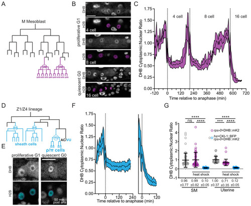
(A) SM lineage schematic. (B) Micrographs of a time-lapse showing SM cells at G1 and G0. (C) Quantification of CDK activity in SM cells (n ≥ 10). (D) Uterine lineage schematic. (E) Micrographs of a time-lapse showing uterine cells at G1 and G0. (F) Quantification of CDK activity in uterine cells (n ≥ 13). (G) Quantification of CDK activity in SM cells and uterine cells following ectopic expression of CKI-1 (hsp>CKI-1:: mTagBFP2) compared to non-heat shock controls and heat shock animals without the inducible transgene (n ≥ 36 cells per treatment). Pseudo-colored nuclei magenta, B; cyan, (E) indicate cells of interest. Scale bars = 10 μm. Dotted line in C and F indicates time of anaphase. Line and shaded error bands depict mean ± SD. Time series measured every 5 min. ns, not significant, ****p≤0.0001. Significance determined by statistical simulations; p-values in Supplementary file 1. |
( |

(A) Schematic of primary (1°) and secondary (2°) fated VPCs. (B) All of the VPCs divide, with the exception of the D cells, to facilitate vulval morphogenesis. (C) Time series of CDK sensor localization in the 1° and 2° VPCs, as measured every 5 min. Note that the D cells are born into a CDKlow state (n ≥ 9 cells). Dotted line indicates time of anaphase. Shaded error bands depict mean ± SD. (D) Representative images of CDK sensor localization in the VPCs from the P6.p 2 cell stage to 8 cell stage. Nuclei (H2B) are highlighted in magenta for non-D cell 1° and 2° VPCs and green for the D cells. Scale bar = 10 μm. |

( |

(A) Schematic of VPC divisions in the L3-L4 larval stage. (B) CDK activity and CKI-1 levels across pseudo-time and DHB ratios for all VPCs (black line) and D cells (dark green line). GFP::CKI-1 fluorescence in VPCs (gray line) and D cell (light green line); n ≥ 93 cells per lineage. (C) Representative images of VPCs at the Pn.p 2-cell stage at G1 and G2 (white asterisk). (D) Representative images of VPCs at the Pn.p 4-cell stage at G1 and G2; early quiescent C cells (cyan arrows) with low levels of GFP::CKI-1. (E, F) Representative images of VPCs at the Pn.p 6- cell stage (E) and 8-cell stage (F); arrows show early quiescent C (cyan) and B cell (dark blue), F cell (magenta), and A cell (purple). (G) GFP::CKI-1 fluorescence in each cell of the VPC lineage (n ≥ 16, except C normal and A early n = 2, E early n = 3). (H) Percentage of cells of each lineage that showed signs of early quiescence and did not undergo their final division. (I) Overexpression of CKI-1 via heat shock causes cells to pre-maturely enter and remain in G0 (n ≥ 36 cells per treatment). Scale bar = 10 μm. ns, not significant, *p≤0.05, ****p≤0.0001. Significance determined by statistical simulations; p-values in Supplementary file 1. |

Related to Figure 4. (A–C) Pseudo-time plots comparing levels of GFP::CKI-1 and CDK sensor ratio in vulval AB (A), CD (B) and EF (C) lineages. (D) Representative single plane confocal micrographs show DHB (top) and GFP::CKI (bottom) localization in uterine cells in proliferative (left, middle) and quiescent cells (G0, right). (E) Representative single plane confocal micrographs show DHB (top) and GFP::CKI (bottom) localization in SM cells lineages in proliferative (top) and quiescent cells (G0, bottom). CKI-1 levels increase later in G2 (right). Inset boxes shown for CKI-1 images are contrast enhanced. (F) DIC and corresponding fluorescent images of rps-0>DHB::mKate2 expression in the AC (arrowhead) and underlying VPCs (bracket) from mid-L3 stage larvae at the Pn.p 2 cell stage (left). Larvae were heat shocked for 2 hr at 32°C (middle) and allowed to recover for 5 hr at room temperature (right). At the Pn.p 8-cell stage, determined by the extent of gonad arm extension and reflection (Sherwood et al., 2005), on average, only 6.86 of the 22 VPCs were present, which is indicative of inappropriate entry into a CDKlow G0 state. (G) Control animals at the L4 stage that were not heat shocked possessed 22 VPCs, shown as confocal merge images from the center (left), top (right, top), and bottom (right, bottom) of a single confocal z-stack. Scale bar = 5 µm. |

(A) Schematic of wild type vulva and vulva with a divided D cell. (B) Representative images at the Pn.p 6 cell stage from CDK sensor strains (top, middle) and endogenous cdt-1::GFP (bottom), showing wild type vulva on the left and vulva with a divided D cell on the right. Penetrance of each phenotype for each strain is annotated on the DHB image. (C) Frames from a time-lapse with a dividing D cell (left; see Figure 3—video 1). Nuclei (H2B) are highlighted in green for the D cell and cyan for the C cells. Green asterisks mark the D cell and cyan asterisks mark the C cell. Scale bar = 10 μm. (D) DHB ratio for C cell, quiescent D cell and dividing D cell (n = 10 quiescent D cells, n = 20 C cell divisions and n = 10 D cell divisions). Dotted line indicates time of anaphase. Line and shaded error bands depict mean ± SD. ns, not significant, **p≤0.01. Significance determined by statistical simulations; p-values in Supplementary file 1. |

Related to Figure 5. (A) Pn.p lineages for respective genotypes listed. Letters indicate whether and in which orientation the four granddaughters further divided, following the nomenclature of Sternberg and Horvitz, 1986. Purple text indicates deviation from wild type condition. (B, C) Bar graphs displaying penetrance of D’ division in animals grown at 25 °C expressing different variants of the CDK sensor or endogenously tagged CDT-1::ZF::GFP or from temperature shifts from 20–28°C (C). (D, E) Representative DIC micrographs of 20 °C control (D) and 28 °C experimental (E) conditions of L4 stage vulva with an extra D cell (D’) division (**) as compared to wild type (*). Scale bar = 5 µm. |

(A) Schematics of inducible zebrafish variants of the CDK sensor fused to mNG (top) or mSc (middle) and a nuclear mask (H2B-FP) separated by a self-cleaving peptide (P2A). Schematic of inducible membrane marker (lck-mNG; bottom). (B) Representative images of HS:DHB-mNG-P2A-H2B-mSC at 18 somites. Scale bar top row = 250 μm. (C, D) Frames of DHB time-lapses taken from the developing tailbud as designated by the orange box shown in the schematic. (E) DHB-mSC and PCNA-GFP puncta during S phase. (F) Dot plot of DHB ratios during interphase states (n ≥ 7 cells from ≥2 embryos). Insets, orange box, are zoom-ins. Scale bar = 20 μm. Line and error bars depict mean ± SD. Numbers in bold are tissues in G0. ns, not significant, **p≤0.01, ****p≤0.0001. Significance determined by statistical simulations; p-values in Supplementary file 1. |

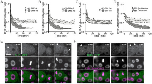
Related to Figure 6. (A) DHB ratio plot from time-lapse of DHB-mNG (gray) and DHB-mSc (magenta) of peak G2 through anaphase and G1 (n> 10 examined for each). Dotted line indicates time of anaphase. |
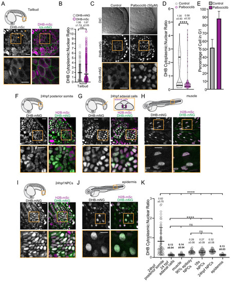
(A) Representative micrographs of CDK sensor (orange arrows and box inset highlights cytosolic CDK sensor localization) and quantification of DHB ratio (B) in the tailbud (n ≥ 160 cells). (C) Representative images of the tailbud of control or 50 µM palbociclib treated embryos (n ≥ 3 embryos). (D) Quantification of DHB in the tailbud (posterior wall and notochord cells excluded) of control or 50 µM palbociclib treated embryos at 20–22 somite stage. (E) Percentage of cells in G1 in the tailbud (posterior wall and notochord cells excluded) of control or 50 µM palbociclib treated embryos. (F–J) Representative micrographs of cells of 24 hpf posterior somites (F; n ≥ 59 cells), adaxial cells (G; n ≥ 50 cells), differentiated muscle at 72 hpf (H; n ≥ 101 cells), notochord progenitors (NPCs) (I; n ≥ 48 cells), and epidermis at 72 hpf (J; n ≥ 32 cells). Insets, orange box, are zoom-ins. Scale bar = 20 μm. (K) Quantification of DHB ratios in zebrafish tissues. Line and error bars depict mean ± SD. ns, not significant, ****p≤0.0001. Orange boxes in schematics (A, F, G and H) depict region shown by the corresponding micrographs in each representative panel. In panel G, a schematic of a transverse section illustrating the position of adaxial cells is shown, but the micrograph is a lateral view. Significance determined by statistical simulations; p-values in Supplementary file 1. |

( |

(A–D) Single-cell traces of CDK activity for all quantified C. elegans (A, B) and zebrafish (C) cell births for CDKinc cells (green) and CDKlow cells (black). DHB ratio of single-cell data (A, C) and mean ± 95% confidence intervals (B) are plotted for each cell analyzed relative to anaphase. A solid green arrowhead indicates a population of fast cycling CDKinc cells while the open green arrowhead indicates a population of CDKinc cells that may be slow cycling in an extended G1 phase. (E) A stacked bar graph of predicted vs. actual cell fates for the D, dividing D, C, and dividing C cells, based on a classifier trained on post-anaphase CDK activity in VPC trace data. (E) A model for the metazoan commitment point argues that the G1/G0 decision is influenced by a maternal input of CKI activity and that CDK activity shortly after mitotic exit can determine future cell fate. |

Related to Figure 8. (A) Predictability of CDK activity on cell fate over time since anaphase. To evaluate the predictability of CDK activity (readout as the ratio of cytoplasmic-to-nuclear intensity of the CDK sensor) on proliferative vs. quiescent cell fate in different cell-cycle phases in C. elegans, we created a Receiver Operating Characteristic (ROC) curve for CDK activity at each time point relative to anaphase. Using the perfcurve function in MATLAB, we calculated the area under the curve (AUC) as the indicator of predictability. (B) Example ROCs that are used to calculate AUC in (A). (C) A histogram of all data points aggregated ≥50 min after anaphase shows that DHB ratios follow a bimodal distribution, suggesting the presence of two populations. (D) Raw data for each cell type/lineage are grouped together and mean time courses generated. (E) The area between these mean trendlines is then calculated. (D’) The assignment between experimental condition groups is randomized, mean time courses are calculated, and (E’) the area between the curves is calculated and recorded (purple line in F’). The randomization procedure, (D’) and (E’), is repeated 100,000,000 times generating a simulated distribution of the difference statistic: (F’). The true value of the difference statistic is compared to the distribution in (F’) generating a p-value (F) corresponding to the proportion of values more extreme than the observed difference statistic (i.e. the number of simulations in the magenta region, divided by the total number of simulations (108)). |