- Title
-
Differential effects of altered patterns of movement and strain on joint cell behaviour and skeletal morphogenesis
- Authors
- Brunt, L.H., Skinner, R.E., Roddy, K.A., Araujo, N.M., Rayfield, E.J., Hammond, C.L.
- Source
- Full text @ Osteoarthritis Cartilage
|
Alterations to movement influence craniofacial skeleton development. A) Flaccid paralysis leads to subluxation of the jaw joint. Brightfield (left hand panels) and Fluorescent images (right hand panels) of lateral views of the head (positioned anterior to left) of 5 day old zebrafish treated with DMSO (top) or MS222 to induce flaccid paralysis (lower panels). Note jaw ‘hanging open’ in MS222 treated larvae due to ‘subluxation’ of the jaw joint. B) Graph showing number of movements per minute in 72, 96 and 120 hours post fertilisation (hpf) sibling and vhl mutant larvae (n = 4,4,8,9,6,8). Statistical test is a 2 tailed Student t test. C) 5dpf craniofacial muscle. A41025 pan-skeletal muscle antibody stain of craniofacial muscle in 5dpf control, myod mutant, 3-5dpf MS222 anaesthetic treated DMB treated and vhl mutant zebrafish. White arrows mark the muscle fibres of the PH. IA, intermandibularis anterior; PH, protractor hyoideus; AM, adductor mandibularis; HI, hyoideus inferior; HS, hyoideus superior; SH, sternohyoideus. D) Muscle paralysis and hyperactivity affect cartilage jaw morphology. Confocal images, oriented anterior to top, of 5dpf cartilage elements of the lower jaw. 5dpf control, myod mutant, 3-5dpf MS222 anaesthetised treated and vhl mutant zebrafish cartilage elements were labelled with Collagen II antibody and DMB treated zebrafish cartilage were visualised using the Tg(Col2a1aBAC:mcherry) transgenic line. MC = Meckel's cartilage, PQ = palatoquadrate, CH = ceratohyal A, anterior; P, posterior; M, medial; L, lateral. (white boxes show regions for which further images are shown in Fig. 2 and Fig. 4). |
|
Muscle paralysis and hyperactivity affect cartilage jaw joint morphology. A) Confocal images of 5dpf zebrafish jaw joints. 5dpf control, myod mutant, 3-5dpf MS222 anaesthetised treated and vhl mutant zebrafish joints were labelled with Collagen II antibody and DMB treated zebrafish cartilage joints were visualised using the Tg(Col2a1aBAC:mcherry) transgenic line. Max projections are shown in the top panel and single z planes of the jaw joint are shown in the lower panel. White arrowheads show the MC overlapping the PQ element. Vertical white lines mark the medial and lateral interzone interval or extent of element overlap between the MC and PQ elements of the jaw joint as measured. Measurements were consistently taken from a mid joint z plane. B). Representative outlines of the 5dpf jaw joint for each condition (n = 4). Meckel's cartilage jaw joint element (Bi), palatoquadrate jaw joint element (Bii) and both elements to show the interaction between the MC and PQ at the jaw joint (Biii). The difference between the interzone interval (μm), on the medial and lateral side of the jaw joint for 5dpf control (n = 13), myod mutant (n = 4), MS222 treated (n = 8), DMB treated (n = 8) and vhl mutant (n = 3) compared in (C). The medial and the lateral interzone intervals are compared between each condition in (D). M, medial; L, lateral. ns = not significant, Significance = P ≤ 0.05. |
|
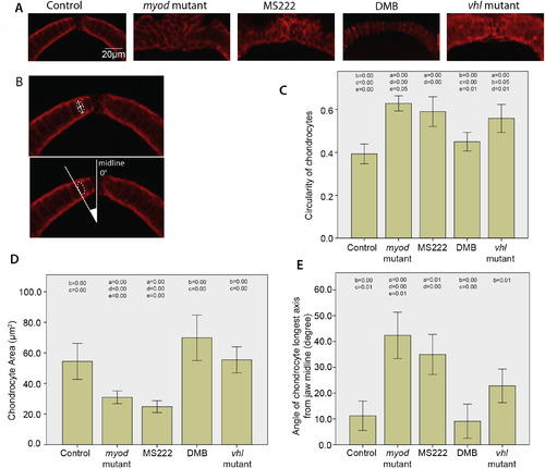
Flaccid paralysis affects the maturation of chondrocytes at the anterior tip of the MC. A) Confocal images of the anterior MC. 5dpf control, myod mutant, 3-5dpf MS222 anaesthetised treated and vhl mutant zebrafish cartilage was labelled with Collagen II antibody and DMB treated zebrafish cartilage was visualised using the Tg(Col2a1aBAC:mcherry) transgenic line. B) Dotted white lines show example cell. Solid white lines mark an example major and minor axis of a collagen II labelled chondrocyte used to calcuate the circularity of the cell (top panel), white lines display angle of cell relative to the midline (bottom panel). C) Graph showing comparison of cell circularity of chondrocytes at the tip of the MC in 5dpf control (n = 30), myod mutant (n = 33), 3-5dpf MS222 anaesthetic treated (n = 26), DMB treated (n = 28) and vhl mutant zebrafish (n = 33) (N.B 1.00 represents a perfect circle). D) Chondrocyte area measurements from cells at the tip of the MC in 5dpf control (n = 29), myod mutant (n = 28), 3-5dpf MS222 anaesthetic treated (n = 34), DMB treated (n = 22) and vhl mutant zebrafish (n = 31). E) Comparison of angle of the major axis of cell relative to the midline in 5dpf control (n = 9), myod mutant (n = 41), 3-5dpf MS222 anaesthetic treated (n = 47), DMB treated (n = 10) and vhl mutant zebrafish (n = 34). For all graphs at least 3 fish were measured per condition with at least 9 cells equally spaced between the insertion points of the intermandibularis muscle measured per fish. P values that are less than or equal to 0.05 between conditions are marked on the graph (in correspondence to the following key), to show which conditions are significantly different to one another. a = control, b = myod mutant, c = 3-5dpf MS222 anaesthetic treated, d = DMB treated, e = vhl mutant zebrafish. Graphs show 95% confidence intervals. |
|
Biomechanical strains correlate with sites of cell maturation. Finite Element models showing locations of Von Mises strain (in microstrain) during mouth opening (IM and PH muscles are applied), closure (AM muscles applied) and in situations where the IM, AM and PH muscles are applied simultaneously to replicate rigid paralysis (A–C). Ventral view (A), Frontal view (B) and Lateral view (C). Confocal stacks of the ventral jaw and jaw joint in the double transgenic line col2a1:mcherry (red) and sox10:eGFP (green) in 5 dpf control zebrafish (D, D′) and immobilised (E,E′) zebrafish. Cells in yellow are seen where the two trangenes are coexpressed. Green cells (which are sox10+ve, col2-ve and therefore less differentiated) are concentrated in the joint regions and in the anterior tip of the MC. Note the altered distribution in the immobilised fish which corresponds to the shape changes observed. Finite Element models showing locations of Maximum principal strain [tension] (F) and Minimum principal strain [compression] (G) in the anterior tip of the MC when the IM muscle alone is applied. Confocal images of the MC anterior tip region (H,I) showing expansion of the distribution of sox10 positive cells in MS222 treated larvae (I) relative to controls (H). |
|
Measurement maximum jaw displacement. A brightfield video of jaw movement (Sup. Vid. 2) is exported into ImageJ. The two most extreme positions of the anterior tip of the MC (black arrowhead) from separate video frames are found and marked (black dots). The lower dot corresponds with the position of the MC of the current frame and the upper dot corresponds with the position of the MC at maximum closure from a previous frame. Maximum jaw displacement is measured in ImageJ between the two points (red line). |
|
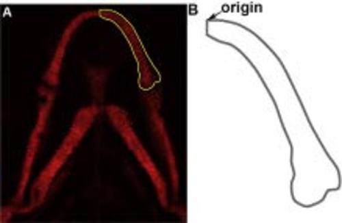
A) Confocal image of the lower jaw, showing the outline collected for morphospace analysis. B) Outline generated showing the origin. |
|
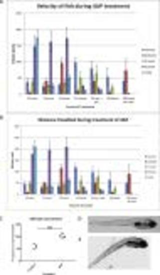
A) Graph showing average velocity of tracked fish treated with doses of 4AP or in the case of control DMSO alone. Tracks were taken from 10 fish per dose and error bars represent 95% confidence intervals. (n = 10) B) Graph to show average distance travelled per fish when tracked over a period of 6 minutes treated with doses of 4AP or in the case of control DMSO alone. Tracks were taken from 10 fish per dose and error bars represent 95% confidence intervals (n = 10). C) Number of mouth openings per minute in control and fish treated with 0.5mM 4AP for 3 h. Measurements taken from 4 fish per treatment. Statistical test is a 2 tailed students t-test P < 0.01. (n = 4) D) Brightfield image of a control larva at 5 dpf. E) Brightfield image of a representative larva treated with 0.1mM 4AP from 3–5 dpf. |


