
- Title
-
Hindbrain V2a Neurons in the Excitation of Spinal Locomotor Circuits during Zebrafish Swimming
- Authors
- Kimura, Y., Satou, C., Fujioka, S., Shoji, W., Umeda, K., Ishizuka, T., Yawo, H., and Higashijima, S.
- Source
- Full text @ Curr. Biol.
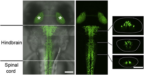
V2a Neurons in the Hindbrain Compound transgenic fish of Tg[chx10:Gal4] and Tg[UAS:GFP] at 3 dpf. The two panels on the left are dorsal views. GFP-expressing neurons are present in the hindbrain and the spinal cord. The asterisks show the GFP signal in the tectums that are originated from GFP-positive cells in the retina. The three panels on the right are cross-sections. The dotted circle demarcates the hindbrain. Scale bar represents 100 μm. |
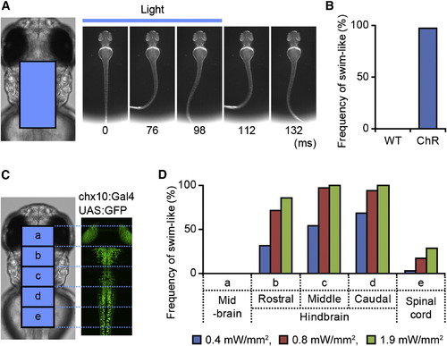
Activation of Hindbrain V2a Neurons Elicits Swimming Compound transgenic fish of Tg[chx10:Gal4] and Tg[UAS:ChR] at 3 dpf were used in the experiments. (A and B) A flash of blue light (0.4 mW/mm2, 100 ms) was applied to the boxed area (left panel in A). This evoked swim-like behavior (right panels in A). (B) Frequencies of eliciting swim-like behavior. “WT” represents wild-type larvae, whereas “ChR” represents larvae that expressed ChR in V2a neurons. n = 35, 7 animals for both cases. (C and D) Region-specific photo stimulations were applied. The hindbrain was divided into three regions (b, rostral; c, middle; d, caudal). Photo stimulations were applied to each region. In addition, photo stimulations were applied to the midbrain (a) and spinal cord (e). (D) Frequencies of eliciting swim-like behaviors with different stimulation sites and different stimulation strengths. The duration of the stimulation was 100 ms. |

Inactivation of Hindbrain V2a Neurons Stops Ongoing Swimming Compound transgenic fish of Tg[chx10:Gal4] and Tg[UAS:Arch] at 3 dpf were used in the experiments. (A–C) Green light (30.5 mW/mm2, 500 ms) was applied to the boxed area (left panel in A) after swimming started (onset latency of the illumination was 200–400 ms). The application of the light stopped swimming (right panels in A). (B) Frequencies of stopping swimming within the illumination periods (500 ms). “WT” represents wild-type larvae, whereas “Arch” represents larvae that expressed Arch in V2a neurons. “No light” represents control experiments in which green light was not applied. In these cases, the duration of swimming was measured after the onset of the electric signal that would turn on illumination with the DMD. In nearly 100% of the trials, the application of green light stopped ongoing swimming in Arch-expressing larvae. Arch: n = 35, 7 animals; WT: n = 25, 6 animals. (C) Mean duration of swimming after the onset of illumination. Bars indicate SE. The dotted line indicates the illumination time. In the case of Arch-expressing larvae, the duration of swimming was significantly shorter (t test; p < 0.001). Arch: n = 35, 7 animals; WT: n = 25, 6 animals. (D and E) Green light (30.5 mW/mm2, 500 ms) was applied in a region-specific manner. (D) Illumination areas are shown. (E) Frequencies of stopping swimming within the illumination periods (500 ms). “No light” represents control experiments in which green light was not applied. n = 25, 5 animals. |
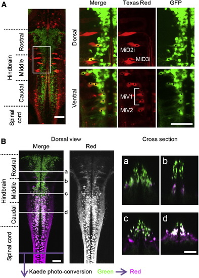
V2a Neurons that Project to the Spinal Cord(A) Texas red-Dextran was backfilled into a compound transgenic fish of Tg[chx10:Gal4] and Tg[UAS:GFP] at 3 dpf. Several ipsilaterally projecting large reticulospinal neurons, including MiD2i, MiD3i, MiV1, and MiV2 neurons, are GFP positive, showing that they are among the V2a neurons. The dots indicate neurons that are double positive for Texas red and GFP. (B) Kaede protein in the spinal cord of Kaede-expressing fish (Tg[chx10:Gal4] and Tg[UAS:Kaede] at 3 dpf) was photo converted by application of violet light to the spinal cord. After photo-converted Kaede (from green to red) was transported from the axons to the somata (8 hr waiting time), the observation was made. Green shows the distribution of green Kaede, whereas magenta shows the distribution of red (photo-converted) Kaede. The majority of V2a neurons in the caudal hindbrain are positive for Red-Kaede. In the more rostral region, the number of Red-Kaede-labeled neurons gradually became smaller. Subpanels of (a)–(d) show cross-sections. Scale bar represents 50 μm. |

Activity of Hindbrain V2a Neurons during Fictive Swimming Compound transgenic fish of Tg[chx10:Gal4] and Tg[UAS:GFP] at 3 dpf were used for electrophysiological recordings. Loose-patch recordings from reticulospinal V2a neurons were made together with VR recordings. (A and B) (A) shows an example of recordings from the small reticulospinal V2a neurons in the caudal hindbrain, whereas (B) shows an example of recordings from the MiV1 neurons. The left panels show the region of the cells that were recorded. The top panel for each figure is a dorsal view, whereas the bottom panel is a cross-section. Middle panels show recordings. The numbers in parentheses indicate the locations of the VR recordings. The right panels show circular plots that depict the phasic relation of V2a neuron spikes to the VR activity. The central time point of a VR activity was assigned a phase value of zero and that of the next VR activity was assigned a phase value of one (Figure S5 C). The phase values of 30 randomly selected spikes are plotted in the circle. The direction of the vector shows the mean of the phase value, whereas the length of the vector shows the strength of the rhythmicity. (C) Histograms of the number of spikes of reticulospinal V2a neurons per VR cycle. The top panel shows a histogram of the small reticulospinal V2a neurons in the caudal hindbrain, whereas the bottom panel shows a histogram of the MiV1 neurons. n = 44 for the former, and n = 14 for the latter. (D) Histograms of the length of the vectors (“r”). The top panel shows the histogram of the small reticulospinal V2a neurons in the caudal hindbrain. In this histogram, only those neurons whose firing frequencies were more than 0.1 are included. n = 20. The middle panel shows the histogram of the MiV1 neurons. n = 14. The bottom panel shows the histogram of the spinal V2a neurons. This figure is shown for comparison purposes. n = 12. |
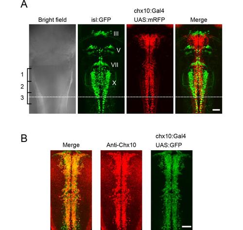
Hindbrain V2a neurons (A), A comparison of V2a neurons and cranial motoneurons in the hindbrain. Triple transgenic fish of Tg[chx10:Gal4], Tg[UAS:mRFP] and Tg[isl1:GFP] at 3dpf. Dorsal views. Nuclei of cranial motoneurons are shown in Roman numerals. The caudal end of the vagal motoneurons (X) is located near the middle of the third muscle segment (dotted line). This was used as a landmark for defining the caudal end of the hindbrain in this study. (B), Immunostaining of Chx10 protein in a compound transgenic fish of Tg[chx10:Gal4] and Tg[UAS:GFP] at 2 dpf. Dorsal views. The distribution of Chx10-positive cells and GFP-positive cells mostly overlap. Scale bar, 50 μm. |
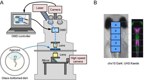
Photo-stimulation of V2a neurons (A), A schematic of the experimental setup. A larva was mounted on agarose with its tail left free. The region and duration of the photo-stimulation is controlled by digital micro-mirror device (DMD) that is attached to the upright epifluorescent microscope. Movements of the larva are monitored from the bottom using a high-speed camera. (B), Demonstration of region-specific illuminations using Kaede transgenic fish (Tg[chx10:Gal4] and Tg[UAS:Kaede] at 3 dpf). Areas boxed with “a–e” correspond to regions of the photo-stimulations in the ChR experiments. In this larva, regions “b”, “d,” and the spinal cord caudal to region “e” were illuminated with violet light. Magenta represents photo-converted Kaede. |
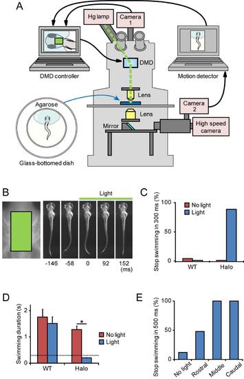
Inactivation of hindbrain V2a neurons stops on-going swimming (A), A schematic of the experimental setup. The setup is essentially identical to that of the ChR photo-stimulation experiments (Fig. S2A), except that it contains a camera2 and computer for motion detection. The light-path from the bottom part is divided into two, with one reaching the high-speed camera and the other reaching camera2. Images of camera2 are digitized in the computer, and larval motion is detected. After detecting motion, an electronic signal is sent to the other computer (DMD controller) to start illumination by controlling DMD. (B) - (E), Inactivation of hindbrain V2a neurons with Halo3. Compound transgenic fish of Tg[chx10:Gal4] and Tg[UAS:Halo3] at 3 dpf were used in the experiments. (B), (C), and (D), Green light (7.6 mW/mm2, 300 ms) was applied to the boxed area (left panel in B) after swimming started (onset latency of the illumination was 200–400 ms). The application of the light stopped swimming (right panels in B). (C), Frequencies of stopping swimming within the illumination periods (300 ms). “WT” represents wild-type larvae, whereas “Halo” represents larvae that expressed Halo3 in V2a neurons. “No light” represents control experiments in which green light was not applied. In these cases, the duration of swimming was measured after the onset of the electric signal that would turn on illumination with the DMD. In 90% of the trials, illumination of the green light stopped on-going swimming in Halo3-expressing larvae. Halo3: n = 27, 6 animals; WT: n = 25, 6 animals. (D), Mean duration of swimming after the onset of illumination. Bars indicate SE. The dotted line indicates illumination time. In the case of Halo3-expressing larvae, the duration of swimming was significantly shorter (t-test; *p <0.001). Halo3: n = 27, 6 animals; WT: n = 25, 6 animals. (E), Green light (7.6 mW/mm2, 500 ms) was applied in a region-specific manner. Illumination areas are the same as the ones shown in Figure 3D. Frequencies of stopping swimming within the illumination periods (500 ms) are shown. “No light” represents control experiments in which green light was not applied. n = 25, 7 animals. |

V2a neurons that project to the spinal cord TexasRed-Dextran was back-filled into a compound transgenic fish of Tg[chx10:Gal4] and Tg[UAS:GFP] at 3 dpf. In the rostral region of the hindbrain, there is no overlap between TexasRed labeling and GFP labeling. In the caudal region of the hindbrain, several small neurons are double positive for TexasRed and GFP. Scale bar, 50 μm. |

Activity of hindbrain V2a neurons during fictive swimming Compound transgenic fish of Tg[chx10:Gal4] and Tg[UAS:GFP] at 3 dpf were used for the experiments. (A) and (B), Electroporations of rhodamin dye into the small V2a neurons in the caudal hindbrain. (A), A representative example. The left panels show lateral views of the labeled neurons. The right panels show dorsal views of the labeled neurons in the hindbrain. The neurons projected both rostrally and caudally. Scale bar, 100 μm. (B), Schematic views showing the trajectories of 12 neurons that were investigated. All of the neurons projected to the spinal cord. In addition, many of the neurons also had axons that projected rostrally in the hindbrain. (C), The method to determine the phase value in the circular plot. VR recordings (top) are rectified and smoothened (middle). The phase values of 0 and 1 are given to a central time point of a VR activity and that of the next VR activity, respectively. Then, phase values are given to spikes of V2a neurons (bottom). (D) and (E), Loose-patch recordings from the small reticulo-spinal V2a neurons in the caudal hindbrain. The numbers in parentheses indicate the locations of the VR recordings. The right panels show circular plots that show the phasic relation of V2a neuron spikes to VR activity. The phase values of 30 randomly selected spikes are plotted in the circles. (F), A whole-cell recording of a MiV1 neuron. The numbers in parentheses indicate the locations of the VR recordings. The right panels show a circular plot that shows the phasic relation of MiV1 neuron spikes to the VR activity. The phase values of 30 randomly selected spikes are plotted in the circles. (G), The apexes of the vectors of the recorded neurons are plotted in a circle. For the small reticulo-spinal V2a neurons in the caudal hindbrain, only those neurons whose firing frequencies were more than 0.1 are included. The phase values in this plot are compensated such that VR recordings would have been made at the position of the recorded neurons by using the value of 0.966 ms/segment. n = 20 for the small reticulo-spinal V2a neurons; n = 14 for the MiV1 neurons; and n = 12 for the spinal V2a neurons. |